


307–758 37
DISPLACEMENT PUMP REPAIR
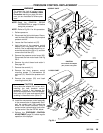
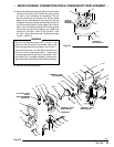
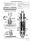
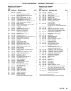
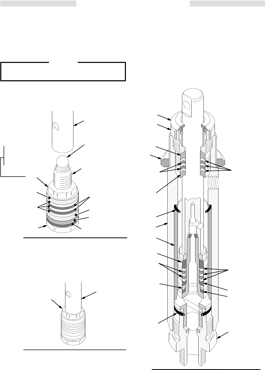
3. Tighten the packing retaining nut (211) against the
piston
valve (222) to 19 ft-lb (27 N.m).
Note
the alignment
of the
piston (222) to the pack
-
ing retainer nut (211). Maintain this alignment
through
Steps 5, 6 and 7.
4. Place
the ball (225)
on the piston valve (222). See Fig
37–1.
CAUTION
Step
5 is critical. Follow the procedure carefully to
avoid damaging the packings by overtightening.
5. Apply one drop of adhesive, supplied, to the piston
valve
threads. Then hand tighten the valve assembly
into
the piston rod just until
the nut (21
1) contacts the
rod.
See Fig 37–1.
211
Fig 37–1
POLY
*212
LIPS F
ACE UP
0029
222
203*
LIPS F
ACE DOWN
215*
225*
APPLY ONE DROP
OF SEALANT T
O
THESE THREADS
224
TORQUE TO
10.5 in-lb (1.2 N.m)
to seat the packing,
and then back of
f and
tighten finger tight.
*210
214*
206*
LEATHER
LIPS F
ACE UP
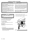
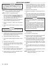
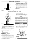
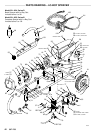
6. Place
the flats at the top of the rod in a vise.
7. Use a wrench to CAREFULLY tighten the nut (211)
onto the piston rod to 19 ft-lbs (25 N.m). See Fig
37–2.
Use two wrenches to maintain the alignment men-
tioned
in Step 7, above.
Fig 37–2
224
211
TORQUE
NUT
AGAINST ROD T
O
19 ft–lb (27 N.m)
DO NOT ALLOW NUT
(211)
T
O MOVE
WHEN
INSTALLING
PIST
ON
ONTO ROD
01238
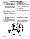
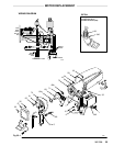
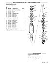
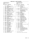
8. Stack the male gland (208*), alternate packings
(213*,207*), and female gland (209*) into the top of
the
cylinder (219). See Fig 37–3.
9. Install
the packing
nut (216) and plug (205), but leave
loose
for now
.
See Fig 37–3.
10. Coat the piston rod and packings with oil. Carefully
slide the assembly INTO THE TOP OF THE
SLEEVE.
NOTE: The
tapered end of the sleeve is the bottom of
it.
See
Fig 38–1.
11. Place a new o–ring (217*) firmly in the cylinder
groove.
See Fig 37–3.
219
Fig 37–3
212*
POLY
LIPS
MUST
F
ACE UP
213*
POLY
LIPS MUST
F
ACE UP
205
*206
LEATHER
LIPS MUST
F
ACE UP
*203
U–CUP SEAL
LIPS MUST
FACE DOWN
215*
214*
*202
*217
*208
*207
LEATHER
LIPS MUST
FACE DOWN
*209
41
218
216
211
TORQUE TO:
67 ft-lb
(90 N.m)
*210
01197