


Overview
3A2988B 7
Overview
The left side of the mix manifold is intended for the major
volume material, or the higher viscosity material if using
a 1:1 volume mix. This side is referred to throughout the
manual as the resin side or “A” side. The right side is
referred to as the hardener side or “B” side.
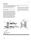
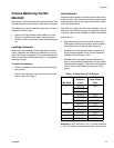
See FIG. 2 to view flow of A and B material inside the
XM PFP Mix Manifold.
The resin and hardener enter the manifold through the
manifold inlet ports. The A material flows through the
manifold to the material outlet port. The injector tube
creates a hollow stream of A material for the B material
to combine with once the hardener exits the injector (P).
The resin and hardener materials enter the mix manifold
outlet (R) before the materials enter the first length of
integrator fluid hose (L). The materials then pass
through the mixer assembly (S) where they are thor-
oughly mixed. Then they pass through a length of mix
hose (T1) where the continue to be lightly mixed before
entering the fluid whip hose (T2) then the gun (U).
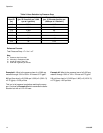
Follow these recommendations for setup (see FIG.1on
page 6):
• Useatleasta1/2in.(12mm)x2ft(0.6m)integra-
tor hose (L) connected to the mix manifold outlet
• Use at least 12 elements in the static mixer after the
integration hose and before the mix hose (T1).
• Useatleasta1/2in.(12mm)x10ft(3.0m)mix
hose (T1) after the static mixer and before the spray
gun.
F
IG. 2: Cutaway View
45
SECTION
A-A
SECTION
B-B
UBKGUZ
Hardener
Combined Material
Resin
ti20091a
Top View
Front View
AB