


Installation
8 3A2988B
Installation
For assistance in setting up a plural component sprayer,
contact your Graco distributor, to ensure that you select
the proper type and size equipment for your system.
Fluid Inlets
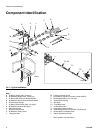
See FIG. 1 on page 6. The A and B fluid inlets are
equipped with 3/4 in. check valves, ball valves, and
3/4 in. x 3/4 in. npt fittings and 3/4 in. x 1/2 in. fitting.
Connect 3/4 in. and 1/2 in. npsm(f) fluid hoses using the
two adapter nipples.
Solvent Inlet
See FIG. 1 on page 6. Connect the solvent supply line
from the solvent pump to the 1/4 npt(m) solvent inlet
valve (H). Use a grounded, Graco-approved hose rated
to withstand the maximum fluid working pressure of the
solvent pump. The solvent chosen must be chemically
compatible with the hose core material.
Fluid Outlet
See FIG. 1 on page 6. Connect the 1/2 in. ID x 2 ft. (min-
imum) integrator hose (L) to the mix manifold fluid outlet
(R). Then connect the static mixer (S) and mix hose (T1)
to the 1/2 npt(f) integrator hose (L). Then connect the
fluid whip hose (T2) to the mix hose and the gun to the
whip hose.
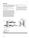
Heated Manifold
See FIG. 1 on page 6. The XM PFP manifold has a 1 in.
thick aluminum plate with brass compression fittings for
1/2 in. OD x 3/8 in. ID nylon hose used to circulate
heated water/glycol and heat the mix manifold.
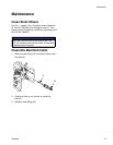
Mounting
To mount the bare manifold, drill four holes in the mount-
ing surface, and secure with four 5/16-18 x 1/2 in.
(50 mm long) screws. Use the manifold as a template
when drilling the holes.
The mix manifold is designed for use on proportioning
pumps with independent drive motors. Do not use this
manifold on a mechanically linked sprayer without
using mechanically linked on/off A and B valves as
this will result in fluid pressures that can rupture equip-
ment and cause skin injection.