


Installation
313258C 5
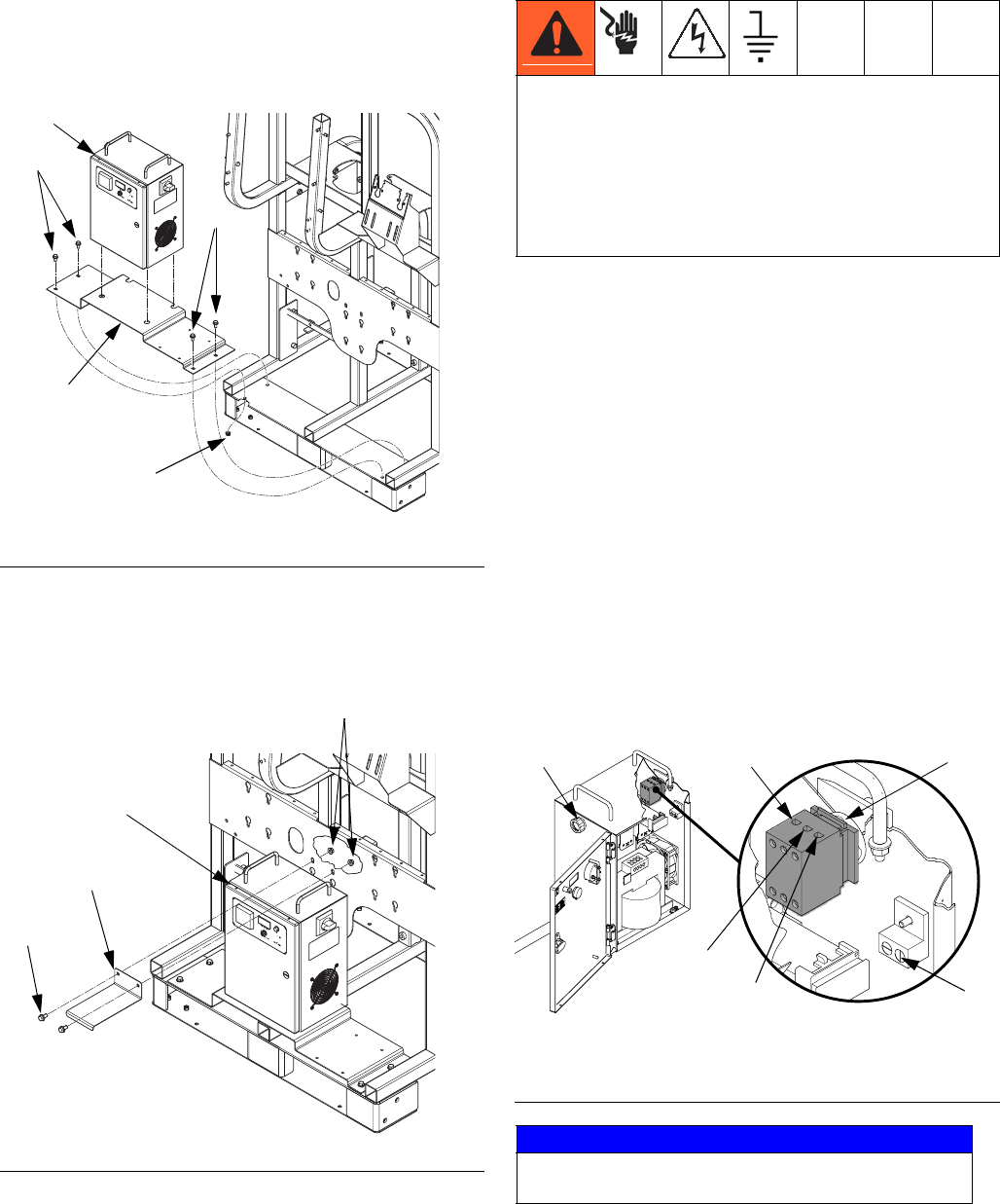
Installation
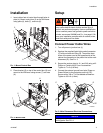
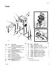
1. Insert rubber feet of control box through holes in
plate (4). Mount control box (2) on the XM frame
using plate (4), bolts (7), and nuts (6).
2. Place bracket (5) on top of the control box (2) and
mount to the XM frame using screws (7) and nuts
(6).
Setup
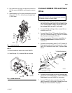
Connect Power Cable Wires
1. Turn off power to junction box (J).
2. Replace the supplied liquid-tight conduit connector
(C) with cord restraint fitting (8). Thread the three
wires of the power cord to the opposite side of the
cabinet for connection to the power inlet at the main
disconnect (D). See F
IG
. 3.
3. Secure the service wires to 1L1 and 3L2 using a #2
Phillips or Pozidriv M3,5 Form 2 screwdriver.
Tighten to 7 in-lb (0.8 N•m).
4. Connect the external ground bond wire (Green or
Green/Yellow) to the protective earth lug (PE).
Secure with a 3/8 or 7/16 flat-bladed screwdriver.
Tighten to 35 in-lb (4 N•m).
F
IG
. 1: Mount Control Box
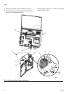
F
IG
. 2: Mount Plate
2
4
7
7
ti20973a
6
5
7
6
2
ti20974a
Installing this equipment requires access to parts that
may cause electric shock or other serious injury if
work is not performed properly. Have a qualified elec-
trician connect power and ground to power switch ter-
minals; see manual 3A2980 and F
IG
. 4 on page 6. Be
sure your installation complies with all national, state,
and local safety and fire codes.
F
IG
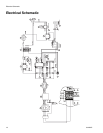
. 3: Main Disconnect Electrical Connections
NOTICE
Route power cable (3) to avoid interference with
moving parts. See F
IG
. 4.
1L1
3L2
3L2
PE
ti19942a
C
D