


Setup
313258C 7
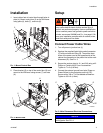
8. Set transformer wire taps in hose heat control box
(2). See manual 3A2980 to verify tap wire connec-
tion.
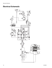
9. Install adapters (16) in dosing valve blocks and use
fittings (14, 15, 17, or 18) to connect heated hose
(1) fluid inlets.
NOTE:
To connect additional hoses see manual 309572.
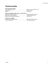
10. Install fittings (12) in remote XM mix manifold.
Connect 24M943 FTS and Power
Wires
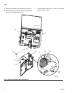
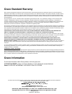
1. Carefully extend FTS probe (H) into the hose sec-
tion from the hose heat control. Do not bend or kink
probe. Insert probe in major volume resin side
on systems which are not 1:1 mix ratio.
2. Connect FTS (9) to fittings (12) on remote XM mix
manifold. See F
IG
. 6.
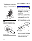
3. Connect fitting (23) to FTS coupler (9a) and fitting
(19 or 20). Connect fittings (21 or 22) to FTS sensor
(9c). Connect fluid hoses to FTS (9).
4. Install one connector (D) between wires. Refer to
Connect Heated Hoses in manual 309572 for
instructions.
5. Connect hose assembly cable (F) to FTS cable (R).
Slide insulator sleeves (S) over connection. Leave
slack (G) in cables as stress relief, to prevent cable
failure.
6. Connect two black power wires from the hose heat
control box (2) to heated hose (1). Refer to Connect
Fluid Hose in manual 3A2980 for instructions.
7. Connect FTS cable from control box (2) to FTS
cable connection of first length of heated hose from
XM sprayer. See illustrations on page 9.
F
IG
. 5: Dosing Valves
F
IG
. 6: XM Mix Manifold
WLD
16
16
14,
15,
17,
or 18
14,
15,
17,
or 18
WLD
23
19 or 20
21 or 22
9c
9a
12
12
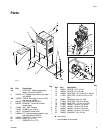
NOTICE
Do not coil hose tighter than the minimum bend
radius of 3 ft (0.9 m). Do not subject hose to exces-
sive weight, impact, or other abuse.
F
IG
. 7: 261670 FTS Kit
ti2684d
H
D
S
S
F
R
G
9c
To XM Mix Manifold
To XM sprayer
9a