


8
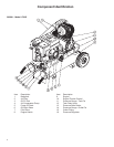
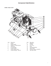
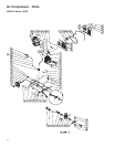
SAFETY RELIEF VALVE: This valve is designed to pre-
vent system failures by relieving pressure from the sys-
tem when the compressed air reaches a predetermined
level. The valve is preset by the manufacturer and
must not be modied in any way. To verify the valve is
working properly, pull on the ring. Air pressure should
escape. When the ring is released, it will reset.
PILOT VALVE: When the toggle is in the upright posi-
tion, all air from the air compressor is vented through
the discharge mufer. This gives an easy start feature.
For normal operation, the toggle is in the 90° position.
AIR INTAKE FILTER: This lter is designed to clean air
coming into the pump. To ensure the pump continu-
ally receives a clean, cool, dry air supply this lter must
always be clean and ventilation opening free from ob-
structions. Replace lter element when necessary.
OIL FILL PORT/VENT: Pour oil into the Oil Fill Port/Vent
when required.
OIL SIGHT GLASS: The Oil Sight Glass displays the oil
level in the pump. The oil level should be at the center
of the Oil Sight Glass. If low, add SAE 30W non-deter-
gent oil.
AIR COMPRESSOR PUMP (Single Stage): To compress
air, the pistons move up and down in the cylinders. On
the downstroke, air is drawn in through the air intake
valves while the exhaust valves remain closed. On the
upstroke, air is compressed, the intake valves close
and compressed air is forced out through the exhaust
valves, into the discharge line, through the pilot valve
and into the air tank.
AIR COMPRESSOR PUMP (Two Stage): A two stage
compressor pump uses two different size cylinders with
the intake valve of the second smaller cylinder linked
to the exhaust valve of the rst larger cylinder. On the
down stroke of the large cylinder, air is drawn through
the intake valve while the exhaust valve remains closed.
On the upstroke, air is compressed, the intake valve
closes and compressed air is forced out through the ex-
haust valve, into the inter cooler and through the intake
valve of the second smaller cylinder on its down stroke.
On the upstroke of the smaller cylinder, the intake valve
closes and the compressed air is compressed a second
time and forced out the exhaust valve into the discharge
line, through the tank check valve and into the air tank.
AIR TANK PRESSURE GAUGE: The air tank pressure
gauge indicates the reserve air pressure in the air tank (s).
PRESSURE REGULATOR: The air pressure coming
from the air tank is controlled by the regulator knob.
Turn the pressure regulation knob clockwise to increase
discharge pressure, and counterclockwise to decrease
discharge pressure.
OUTLET PRESSURE GAUGE: The outlet pressure
gauge indicates the air pressure available at the outlet
side of the regulator. This pressure is controlled by
the regulator and is always less or equal to the air tank
pressure.
AIR TANK DRAIN VALVE: The drain valve is used to
remove moisture from the air tank(s) after the air com-
pressor is shut off.
To open the drain valve, turn the knob coun-
terclockwise.
OIL FILL PORT
OIL SIGHT GLASS