


10 308645
Service
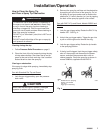
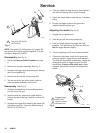
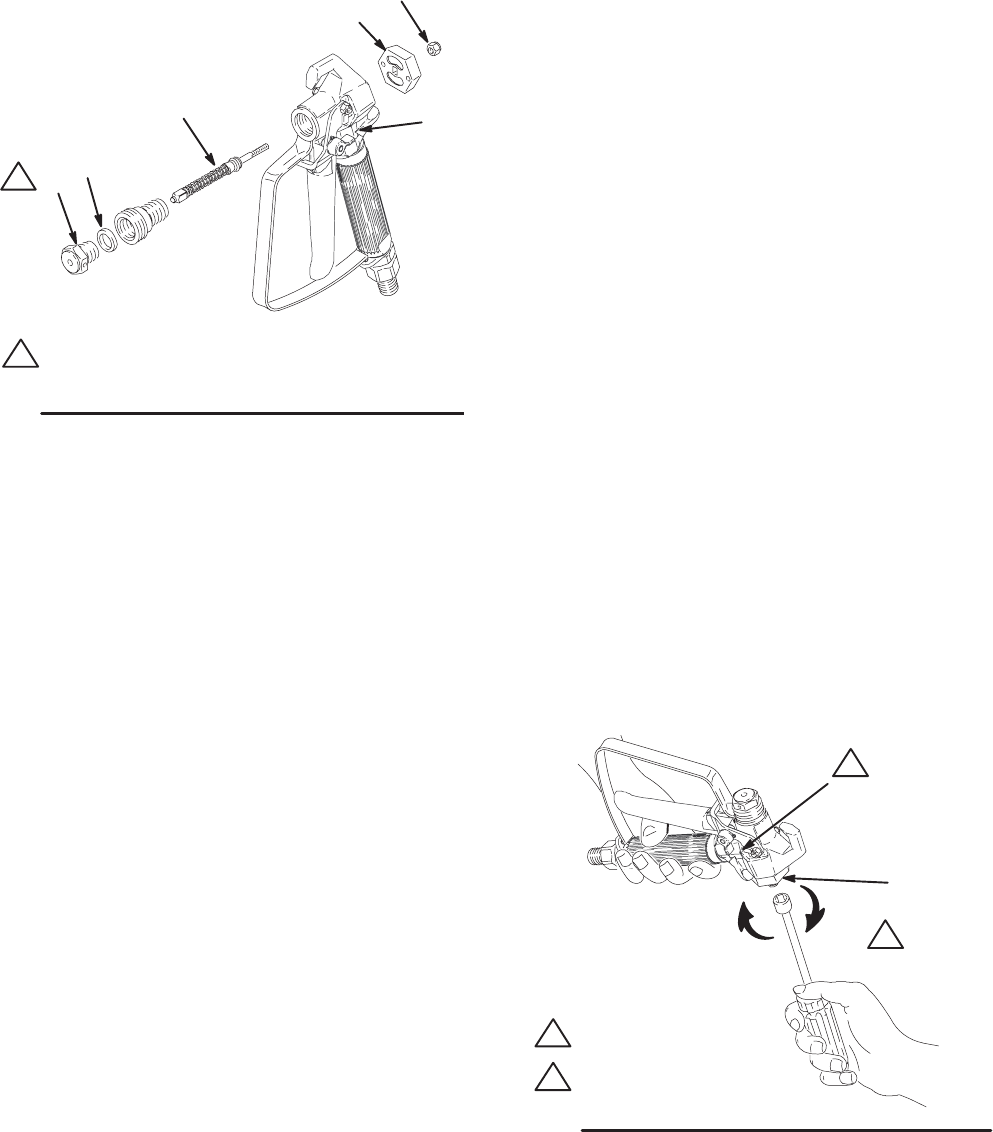
Fig. 8
23
1
Torque to 26–32 ft-lb
(35–43 N.m)
A
B
C
D
1
4
05970
NOTE: The needle (C), diffuser/seat (A), gasket (B)
and locknut (D) must be replaced together. They are
included in Repair Kit 218070.
Disassembly (See Fig. 8)
1. Follow the Pressure Relief Procedure on page
5.
2. Remove the tip guard assembly. See Fig. 2.
3. Squeeze the trigger while unscrewing the diffuser/
seat (A) and gasket (B).
4. Remove the locknut (D) and end cap (23).
5. Tap the rear of the gun with a plastic mallet to
push the needle assembly out the front.
Reassembly (See Fig. 8)
1. Guide the threaded end of the needle assembly
into the front of the gun.
2. Install the end cap, aligning its guides with the
holes in the rear of the gun. Install the locknut (D)
loosely.
3. Squeeze the trigger while installing the gasket (B)
and diffuser/seat (A). Torque the diffuser seat to
26–32 ft-lb (35–43 N.m).
4. If the gun handle (6) was removed, hand tighten it
into the fluid housing (26); it should fit easily.
5. Adjust the needle before using the gun. Procedure
below.
6. Be sure the trigger guard and tip guard are
installed before using the gun.
Adjusting the needle (See Fig. 9)
1. Engage the gun safety latch.
2. Hold the gun with the nozzle straight up.
3. Hold your finger against the trigger with light
pressure. Turn the locknut (D) clockwise until you
feel the trigger depress slightly.
4. Turn the adjusting nut 3/4 turn counterclockwise.
5. Connect the fluid hose. Install the tip guard and
prime the system. Trigger the gun and release it.
The fluid flow should stop immediately. Engage the
safety latch and try to trigger the gun. No fluid
should flow. If the gun fails either test, relieve
pressure, disconnect the hose and readjust the
needle.
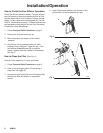
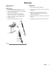
Fig. 9
1
D
2
1
2
Engage trigger
safety latch
Arrows indicate
clockwise turn
05972