


6 308415
Setup
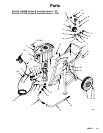
Supplied Components
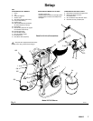
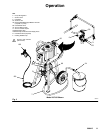
Refer to Fig. 2.
WARNING
A red-handled bleed-type master air valve (30) and
a fluid drain valve (D) are supplied. These accesso-
ries help reduce the risk of serious injury, including
fluid injection and splashing of fluid in the eyes or
on the skin, and injury from moving parts if you are
adjusting or repairing the pump.
The bleed-type master air valve relieves air trapped
between this valve and the pump after the valve is
closed. Trapped air can cause the pump to cycle
unexpectedly. Locate the valve close to the pump.
The fluid drain valve assists in relieving fluid pres-
sure in the displacement pump, hose, and gun.
Triggering the gun to relieve pressure may not be
sufficient.
D The red-handled bleed-type master air valve
(30) is required in your system to relieve air trapped
between it and the air motor when the valve is
closed (see the WARNING above). Be sure the
bleed valve is easily accessible from the pump, and
is located downstream from the air regulator (5).
D With a wrench, loosen and remove the female air
line coupler (71). Screw it onto the main air hose
(A). Leave the mating coupler (70) attached to the
air manifold (32)
D The air regulator (5) controls pump speed and
outlet pressure by adjusting the air pressure to the
pump. Locate the regulator close to the pump, but
upstream from the bleed-type master air valve.
D The air manifold (32) provides ports for connect-
ing lines to air-powered accessories.
D The air relief valve (73) opens automatically to
prevent overpressurization of the pump.
D The fluid filter (8) includes a 60 mesh (250 mi-
cron) stainless steel element to filter particles from
the fluid as it leaves the pump. It includes the fluid
drain valve (D), which is required in your system to
relieve fluid pressure in the hose and gun (see the
WARNING above).
D The suction hose (7) and tube (24) allow the
pump to draw fluid from a 19 liter (5 gallon) pail (E).
D Two fluid shutoff valves (69) are supplied at the
fluid filter outlets. Attach the fluid hose (103) to one
of the valves. Keep the other valve capped and
closed at all times unless you are using a second
hose and gun.
Connect the Suction Hose
Apply thread sealant to the suction hose (7) and screw
it into the bushing (22) at the pump’s fluid intake.
Screw the suction tube (24) onto the other end of the
hose. Attach the inlet strainer (25) to the tube.
Connect the Fluid Hoses and Gun
NOTE: Model 237158 includes a Hose and Gun Kit
(101), which supplies fluid hoses, a spray gun, and
connecting parts (ref. nos. 102106). If you supply your
own fluid hoses and gun, be sure they are properly
sized and pressure-rated for your system. Use only
electrically conductive hoses.
1. Connect the main fluid hose (103) to one fluid
shutoff valve (69) at the fluid filter (8) outlet.
2. Screw the nipple (105) into the other end of the
main fluid hose (103).
3. Screw the short whip hose (104) onto the nipple
(105).
4. Screw the whip hose (104) onto the fluid inlet of
the spray gun (102).