


10 309662
Displacement Pump Repair
Removal
To reduce risk of injury due to sprayer starting
unexpectedly, shut off engine before performing
checks or service.
WARNING
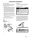
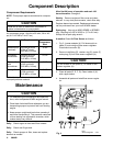
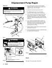
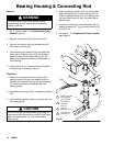
1. Fig. 4. Flush sprayer. Remove suction hose elbow
(150a), pump outlet hose (A) and drain hose (64).
Fig. 4
ti12869a
27
63
22
3
150a
A
64
85
159
158
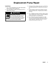
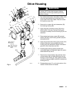
MOVING PARTS HAZARD
To reduce risk of amputating fingers,
keep fingers away from connecting rod
and pin while jogging engine.
WARNING
0407
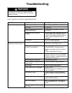
Torque to 20 ft--lb (27 N.m)
Fig. 5
38
23
37
128
27
38
201
128
61
1
1
2
3
2
Back of pump
Cutaway view shows how pin (38) goes
through connecting rod
3
3
2. Fig. 5. Start engine. Jog flow control between
PRIME and OFF until connecting rod stops near
bottom of stroke. Shut off engine.
3. Loosen two quick disconnect screws (27).
4. Pry retaining spring (37) up on connecting
rod (128). Push pin (38) out with a screwdriver.
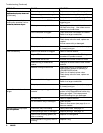
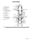
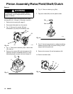
5. Fig. 6. Remove cover (C) to control housing (54)
by remo ving four screws (12). Detach pressure
transducer cord (63, Fig. 4) from control board (9)
at port (D). Remove pre ssure transducer cord from
control box.
6. Fig. 4. Remove air hoses (158) and (159) from
prime valve manifold (85). Note correct air hose
connection to ports on air cylinder (22). Use 5/16
inch wrench to hold ring on hose fitting while
removi ng hose from fitting.
7. Support w eight of pump (3) and remove two quick
disconnect screws (27).
8. Unscrew assembled dump valve manifold (85) and
air cylinder (22) from pump (3).
Fig. 6
ti3007b
12
D
9
C
54
Repair
See page 12 for pump repair instructions.