


309662 11
Displacement Pump Repair
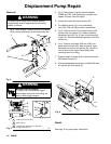
Installation
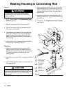
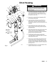
1. Fig. 4. Screw assembled dump valve manifold (85)
and air cylinder (22) into pump (3).
2. Fig. 5. Pull piston rod (201) out of pump (3) 2 to 3
inches (50 to 75 mm).
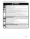
WARNING
MOVING PARTS HAZARD
If pin works loose, parts could break off
due to force of pumping action. Parts
could project through the air and result in
serious injury or property damage. Make sure pin
and retaining spring are properly installed.
3. Lift pump (3) into position and push in pin (38). Be
sure re taining spring (37) snaps down over end of
pin.
4. Support w eight of pump (3) and fasten two quick
disconnect screws (27). Torque screws to 20 ft-lb
(27 N.m).
5. Fig. 4. Reattach air hoses (158) and (159) to prime
valve manifold (85). Ensure air hoses are attached
to the correct port on air cylinder (22).
6. Fig. 6. Route the pressure transducer cord (63,
Fig. 4) to the control box and attach to port (D) on
control board (9). Assemble cover (C) to control
housing (54) using four screws (12).