


6 308–367
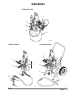
Installation
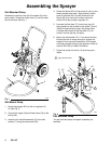
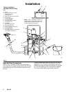
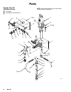
Fig. 4
03146
KEY
A Pump
B Bleed-Type
Master Air V
alve
(required for pump)
C
Air Supply Line
D
Master Air V
alve (for accessories)
E
Air Line Filter
F
Pump Air Regulator
G
Gun Air Regulator
H
Fluid Drain V
alve (required)
J
Fluid Suction Line
K
Fluid Filter
L
Gun Fluid Supply Hose
M
Gun Air Supply Hose
N
Air-Assisted Airless Spray Gun
P
Air Line Lubricator
R
Fluid Intake Elbow
Y
Ground Wire (required; see page 5
for installation instructions)
Typical Installation –
Cart Mount Model Shown
NOTE: Some components shown are
included with the sprayer,
depending on the
model.
Refer to the
parts lists on pages 10–15
for
parts included in your sprayer
.
A
B
C
DE
F
G
H
JK
L
L
M
M
N
P
R
Y
Hose and Gun Connections
Refer
to Fig. 4. Connect one end of the fluid hose (L)
to the fluid filter (K) outlet and the other to the fluid inlet
of the spray gun (N). Do not install the spray tip in the
gun yet.
Close the bleed-type master air valve (B) and the air
regulators (F
, G). Connect a grounded air hose (M)
between the outlet of the gun air regulator (G) and the
air inlet of the spray gun (N). The pump air regulator
(F) is connected to the pump (A) with a hose (C).