


6 308-230
Installation
General Information
1. The T
ypical Installations shown on pages 7 and
8 are only a guide for selecting and installing sys
-
tem components. Contact your Graco distributor or
Graco T
echnical Assistance (see back page) for
assistance in planning a system to suit your needs.
2.
Always use Genuine Graco Parts and Accesso
-
ries, available from your Graco distributor
. Refer to
the Product Data Sheet for the pump, Form No.
305–528. If you supply your own accessories, be
sure they are adequately sized and pressure rated
for your system.
3.
Use a compatible, liquid thread sealant or
r
tape on all male threads. T
ighten all connections
firmly to avoid air or fluid leaks.
Do not over-
tighten plastic threads.
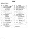
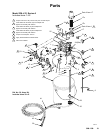
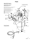
4.
Reference numbers and letters in parentheses re
-
fer to the callouts in the Figures and the parts lists
on pages 12–17.
T
OXIC FLUID HAZARD
Hazardous fluid or toxic fumes can
cause serious injury or death if splashed
in the eyes or on the skin, inhaled, or
swallowed.
1. Read T
OXIC FLUID HAZARD
on page 3.
2.
Use fluids and solvents which are compatible
with the equipment wetted parts. Refer to the
T
echnical Data
section of all equipment manu
-
als. Read the fluid and solvent manufacturer
’s
warnings.
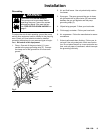
WARNING
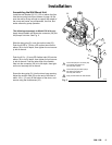
Accessories
A bleed-type master air valve (B) is required in
your system to relieve air trapped between this
valve and the pump. Trapped air can cause the
pump to cycle unexpectedly
, which could result in
serious injury
, including splashing in the eyes or on
the skin, injury from moving parts, or contamination
from hazardous fluids.
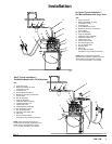
A fluid drain valve (J) is required in your system to
relieve pressure in the hose if it is plugged. (The
fluid recirculation valve supplied with Models
236–870, 224–833, and 236–412 will serve this
purpose.) The drain valve reduces the risk of seri
-
ous injury
, including splashing in the eyes or on the
skin, or contamination from hazardous fluids when
relieving pressure. Install the valve close to the
pump’
s fluid outlet.
WARNING
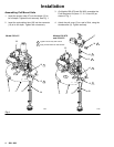
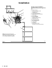
1.
Install the air line accessories as shown in Figs. 3
and 4. Mount these accessories on the wall or on a
bracket. Be sure the air line supplying the acces
-
sories is grounded.
a.
Locate one bleed-type master air valve (B)
close to the pump and use it to relieve trapped
air
. See the
WARNING
above. Locate the oth
-
er master air valve (E) upstream from all air
line accessories and use it to isolate them dur
-
ing cleaning and repair
.
b.
The air line filter (F) removes harmful dirt and
moisture from the compressed air supply
.
2.
Install an electrically conductive, flexible air hose
(C) between the accessories and the pump. Use a
minimum 1/4” (6.3 mm) ID air hose. Screw an air
line quick disconnect coupler (D) onto the end of
the air hose (C)
.
Do not connect the coupler (D) to
the air inlet fitting (22, see Figs. 1 and 2) yet.
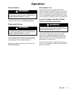
Hose Connections
1. Read
the entire spray gun manual before connect
-
ing the hoses and operating the sprayer
.
2.
Connect a fluid hose (N) between the pump fluid
outlet fitting and the fluid inlet of the spray gun (R).
See Figs. 3 and 4.
3.
Connect an electrically conductive air hose (P) be
-
tween the outlet fitting of the gun air regulator (G)
and the air inlet of the spray gun (R).
PTFEPTFEPTFE