


311937E 5
Reassembly
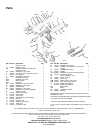
1. Install the tube gasket (22) in the gun. Hand tighten the
fluid tube connector (16a) into the gun’s fluid inlet. Anti-
gens the air inlet fitting (17) and screw (20). Torque the
fluid tube connector to 150-160 in-lb (17-18 N•m). Torque
the air inlet fitting to 175-185 in-lb (20-21 N•m). Torque the
fluid tube bracket screw to 50-60 in-lb (6-7 N•m).
2. Install the inline fluid filter (24) into the base of the fluid
tube (16). Screw the fluid inlet fitting (25) into the base of
the tube. Torque to 175-185 in-lb (20-21 N•m).
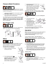
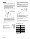
3. Place the new u-cup (7) on the seal installation tool (28),
with the u-cup lips facing the tool. Push the u-cup into the
back of the gun until you feel a definite snap.
4. Lubricate the front end of the air valve assembly (8).
Gently slide the air valve assembly into the back of the
gun, passing through the u-cup (7), as far as it will go. Be
careful not to damage the u-cup.
5. Slide the seat (10) onto the shaft (9). Be sure that the
tapered end of the seat is toward the thicker end of the
shaft. Carefully insert the shaft (9) and seat (10) in the air
valve (8).
6. Install the two springs (15 and 19). Screw the spring cap
(11) into the back of the gun body. Torque to 175-185 in-lb
(20-21 N•m).
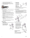
7. Lightly lubricate the needle assembly o-rings and shaft
where the packing slides. Be sure that the o-ring (2a) is in
place in the gun body (1).
8. Insert the fluid needle assembly (2) into the front of the
gun. Use the nut driver (29) to screw the fluid needle
assembly into the gun body (1) and torque to 50-60 in-lb
(6-7 N•m).
9. Install the trigger (3), pivot pin (13), and nut (14). Use low
strength thread locker and be sure that the brass piece of
the fluid needle assembly (2) is behind the trigger.
Lubricate both sides of the pivot pin where the trigger
contacts the pin and lubricate the boss on both sides of
the gun where the trigger contacts the gun body. Torque
the nut to 20-30 in-lb (2-3 N•m).
10. Trigger the gun to pull the needle back while you screw
the diffuser assembly (5) into the gun body (1) using the
gun tool (30). Torque to 155-165 in-lb (18-19 N•m). When
properly tightened, the flange will bottom out on the gun.
11. Attach the guard (6) and spray tip (33), page 2.
Technical Data
*All readings were taken with fan valve fully closed, (full fan size) at
20 psi (140 kPa, 1.4 bar) and 100 psi (0.7 kPa, 7 bar) and at the
assumed operator position. Sound Power tested to ISO 9614-2.
Tranlated Manuals
Translated manuals can be obtained from a distributor
or by visiting www.graco.com.
ti6578a
7
28
Lubricate lightly.
Lips face out of gun body.
3
8
3
8
29
2
2a
1
ti6575a
Maximum Working Fluid Pressure 4000 psi
(28 MPa, 280 bar)
Maximum Working Air Pressure 100 psi
(0.7 MPa, 7 bar)
Maximum Working Fluid Temperature 110° F (43° C)
Fluid inlet 1/4-18 npsm
Air Inlet 1/4-18 npsm
Gun Weight 16 oz (450 grams)
Sound Pressure*: 20 psi (140 kPa, 1.4 bar) 66.9 dB(A)
Sound Pressure*: 100 psi (0.7 kPa, 7 bar) 80.0 dB(A)
Sound Power*: 20 psi (140 kPa, 1.4 bar) 76.8 dB(A)
Sound Power*: 100 psi (0.7 kPa, 7 bar) 89.9 dB(A)
Wetted Parts: Stainless Steel, Carbide, Ultra High Molecular Weight
Polyethylene, Acetal, PTFE, Nylon, Flouroelastomer
Spanish - 311939 Estonian - 311957
French - 311938 Latvian - 311958
Dutch - 311941 Lithuanian - 311956
German - 311950 Polish - 311951
Italian - 311940 Hungarian - 311954
Turkish - 311942 Czech - 311953
Greek - 311943 Slovakian - 311959
Croatian - 311955 Portuguese - 311944
Danish - 311948 Finnish - 311946
Chinese - 311960 Swedish - 311947
Japanese - 311961 Norwegian - 311949
Korean - 311962 Russian - 311952