


308131 27
Service
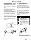
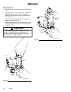
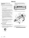
Fig. 18
7
35
37a
37b
18a
18
37
F
3
18b
18c
18f
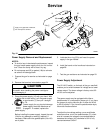
G
Apply a very light coat of lubricant
Do not expose to solvents
0384B
B
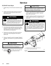
Power Supply Removal and Replacement
NOTES:
D To avoid a loss in electrostatic performance, inspect
the gun handle power supply cavity for dirt or mois-
ture. Clean the cavity with a clean, dry rag.
D Do not expose seal (B) or gasket (18a) to solvents
as solvent will damage them.
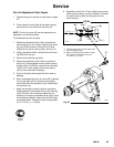
1. Prepare the gun for service as instructed on page
22.
2. Remove the barrel as instructed on page 24.
CAUTION
Be careful when handling the power cartridge to
avoid damaging it.
3. Grasp the power supply (18) with your hand. With
a gentle side to side motion, pull the power supply
free from the gun handle (7), then pull it straight
out. See Fig. 18.
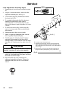
4. Inspect the power supply for any physical damage.
Check the power supply electrical resistance as
instructed on page 21. If needed, replace the
power supply.
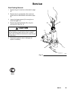
Before installing the power supply, inspect the seal
(18e) for any damage or swelling; replace it if
necessary. Make sure the gaskets/pads (18a–18f)
are in place.
5. Lubricate the o-ring (37a) and insert the power
supply in the gun handle.
6. Install the barrel on the handle as instructed on
page 28.
7. Test the gun resistance as instructed on page 20.
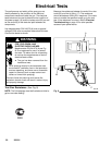
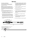
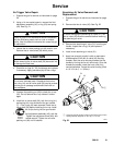
Power Supply Adjustment
The KV HI/LO switch, on the back of the gun manifold,
enables you to switch between full voltage and a lower
voltage output. The lower voltage is factory set at 60
kV, but can be adjusted.
The power supply may be equipped with either a
potentiometer or a two position jumper pin. If you have
the jumper pin style, place the pin in either the 45 kV
or 60 kV position. If you have the potentiometer style,
follow the directions below.
To adjust the low voltage setting, use a small blade
end screw driver to turn the potentiometer (G), clock-
wise to increase the voltage or counterclockwise to
decrease the voltage; fully clockwise is 80 kV, fully
counterclockwise is 45 kV.