


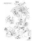

System Component Information
VI.
Using the
G700N
Air Spray Gun
1.
2.
3.
4.
5.
6.
7.
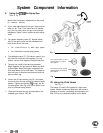
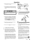
Refer to Fig. 3.
Make initial fluid and air adjustments at the pump
for maximum efficiency.
If you make adjustments at the gun, take noted of
what you do. Then, if the results are not satisfac-
tory, you can easily return the gun to its previous
adjustment. Steps 3 and 4 explain the gun adjust-
ments.
Fan pattern adjusting valve (E). Normal adjust-
ment is the valve turned out fully clockwise and
then turned IN two full turns.
a.
Turn counterclockwise to widen spray pattern.
b.
Turn clockwise to narrow spray pattern.
Fluid adjusting valve (F). This valve is used in sys-
tems that do not have a fluid regulator. For this
system, use the fluid regulator to adjust fluid flow.
The gun has a built-in lead and lag operation.
When triggered, the gun emits air before the fluid
is discharged. When the trigger is released, the
fluid stops before the air flow stops. This helps as-
sure the spray is atomized and prevents fluid buil-
dup on the air cap.
Loosen the air cap retaining ring (G), and rotate
the horns of the air cap to obtain the desired spray
position. Tighten the retaining
ring
snugly, but do
not over-tighten. See Fig. 4 for how to obtain a ver-
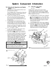
tical or horizontal spray pattern.
Clean and lubricate the gun as instructed in the
separate gun manual, 307-452.
Fig. 3
Air cap horns shown
horizonta
which produces a vertical
spray pattern
Air cap horns shown vertical
which produces a horizontal
spray pattern
Fig. 4
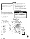
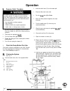
VII. Using the Fluid Heater
See Fig. 6.
The heater (3) used in this system is a high mass
heater. Always circulate the fluid when the heater is
operating to prevent overheating and damaging the
fluid. Do not use catalyzed material in this heater.
6
308-448