


309412 13
Pressure Control
Control Board
Removal
1.
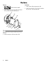
Relieve pressu re; page 4.
2. Fig.8. Remove four screws (54) and
display/cover (52). Pull d isplay connector wings
(A) open on PC board and pull display connecto r
out.
3. Remove 2 screws (139).
4. Fig. 15. Disconnect at control board (302):
D Lead (D) from potentiometer .
D Lead (E) from transducer.
D Lead (B) from On/Off Switch connector.
5. Fig. 8. Remove five s crews (122) from control
board and ground wire screw (122).
6. Remove connector (Y) at backside of pressure
control. Remove jam nut (Z) and control board
(302).
Installation
When installing replacement control board, follow
instructions with control board to set model type.
1. Fig, 8. Install control board (302) and jam nut (Z).
Install connecto r (Y) at backside of pressure
control.
2. Install ground wire and control board (302) with
six screws (122).
3. Fig. 15. Connect to contro l board (302):
D Connect ON/OFF switch connector (B).
D Lead (E) to transducer.
D Lead (D) to potentiometer.
4. Fig. 8. Push display connector into PC board close
display connector wings (A) on PC board. Install
display/cover (52) with four screws (54).
Pressure Control Transducer
Removal
1.
Relieve pressu re; page 4.
2. Fig. 8. Remove four screws (54) and
cover (52).
3. Disconnect lead (E) from control board (302).
4. Remove tw o screws (141) and guard (147). Care-
fully pull transducer connector through rubber
gromme t (145).
5. Remove pressure control transducer (61q) and
packing o-ri ng (61p) from filter housing (61e).
Installation
1. Fig. 8. Install packing o-ring (61p) and pressure
control transducer (61q) in filter
housing (61e). Torque to 30--35 ft-lb.
2. Carefully feed transducer connector through
rubber grommet (145). Install guard (147) with two
screws (141).
3. Connect lead (E) to motor control board (302).
4. Install cover (52) with four screws (54).
Pressure Adjust Potentiometer
Removal
1.
Relieve pressu re; page 4.
2. Fig. 8. Remove four screws (54) and
cover (52) and two screws (139).
3. Disconnect lead (D) from control board (302).
4. Loosen set screws on potentiometer knob (50) and
remove knob, shaft nut, lockwasher (310) and
pressu re adjust potentiometer (310).
5. Remove spacer (74) from potentiometer (310).
Installation
1. Install spacer (74) on potentiometer (310).
2. Fig. 8. Install pressu re adjust potentiometer (310),
shaft nut, lockwasher (310) and potentiometer
knob (50).
a. T urn potentiometer shaft (310) clockwise to
internal stop. Asse mble potentiometer knob
(50) to strike pin on plate (29).
b. After adjustment of step a., tighten both set
screws i n knob 1/4 to 3/8 turn after contact
with shaft.
3. Connect lead (D) to control board (302).
4. Install plate (29) with two screws (139).
5. Install cover (52) with four screws (54).