


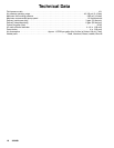

12 309489
Service
Displacement Pump Repair
Before you start:
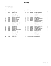
1. A packing repair kit, part no. 946761 is available.
This kit includes two glands and eight packings for
the motor as well as o-rings, packings, and wash-
ers for the displacement pump. For the best re-
sults use all the parts in the kit.
2. Clean all parts as you disassemble them, using a
compatible solvent, and inspect for wear or dam-
age. Replace parts as necessary.
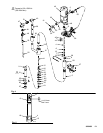
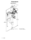
Intake Valve (See Fig. 4)
WARNING
To reduce the risk of serious injury whenever you
are instructed to relieve pressure, always follow the
Pressure Relief Procedure on page 8.
1. Relieve the pressure.
2. Unscrew the intake valve housing (27).
3. Remove the ball stop pin (24). Inspect the ball (25)
and seat (23) for nicks or scratches.
4. Replace the ball and/or seat if it is damaged, as
damaged parts do not seal properly and may
cause poor pump performance.
5. If no further service is needed reassemble the
intake valve. Be sure the ball stop pin (24) is
reinstalled in the proper holes. See Check Valve
Adjustment at right.
Piston
6. Unscrew the riser tube (13) from the pump base.
Clean the tube and inspect it for wear by holding it
up to a light at a slight angle. If you see wavy lines
or scratches where the piston travels, replace the
tube as it will not seal well with the new piston
packings and the pump will perform poorly.
7. Loosen the locknut (15) and unscrew the piston
body (16) from the connecting rod (14).
8. Disassemble and clean all parts.
9. Reassemb le the piston, using all the new parts
from the kit and any other new parts needed. Oil
the leather packings (20*) first. Then, reassemble
the parts on the piston seat (21) in this order;
backup washer (18), leather packing (20*), spacer
(19) with a new o-ring (22) installed on it, another
leather packing (20*), and backup washer (18*).
NOTE: To replace the th roat packings, follow the steps
given in your separate air motor manual supplied,
before continuing with this pro cedure.
10. Apply sealant to the threads of the seat (21) and
screw onto the piston body (16). Screw th e piston
onto the connecting rod (14) and adjust the ball
travel as instructed in Check Valve Adjustment,
below. Tighten the locknut (15).
11. Check the o-ri ng (11) in the pump base and re-
place it if necessary.
12. Lubricate the piston packings and the inner wall at
the top of th e riser tube (13). Wrap the packings
with a guide collar made of 1/64 in. maximum
thickness shim stock or metal sheeting. Using a
turning motion, work the first leather packing into
the riser tube. Remove the guide co llar and push
the riser tube up and screw it into the base. Torque
the tube to 100--150 ft-lb (135--204 NSm).
Reassembly
1. Be sure the check valves are properly adjusted.
See below.
2. Reinstall the intake valve.
3. Reconnect the pump’s ground wire to a true earth
ground.
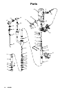
Check Valve Adjustment
These pumps have adjustable fluid intake and piston
ball checks, which are factory-set for medium viscosity
fluids.
To change the piston ball travel (see Fig. 5) loosen
the lock-nut (15). Turn the piston body (16) counter-
clockwise to increase and clockwise to decrease.
Medium viscosity fluids should have a 3/16 in (5 mm)
ball travel. Decreasing the ball travel minimizes surging
at stroke changeover, but too short a ball travel re-
stricts the flow and slows down the pump.
To change the intake valve ball travel, mo ve the ball
stop pin (24) to a higher or lower set of holes. Use th e
middle holes for medium vi scosity fluids.