


6 309489
Installation
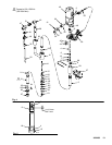
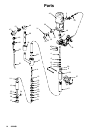
NOTE: Reference numbers and letters in parentheses
in the text refer to callouts in the figure illustrations and
the parts drawing.
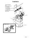
The T ypical installation shown on page 7 is only a
guide to electing and installing require d and optional
accessories. For assistance in designing a system to
suit your needs, contact your Graco representative.
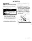
Mount the pump to suit the type of installation planned.
The pump dimensions and mounting hole layout are
shown on page 17.
Pail and Drum Length Pumps
Install the pump in the drum or pail, using a suitable
cover, bung adapter, or mounting clamp. The pump
must be 1/2 in. (13 mm) off the bottom of the pail or
drum.
The pump has a by--pass tube, route the tube back to
the supply container.
NOTE: In a closed-head drum, be sure to loosen the
vent plug in the drum cover to prevent formation of a
vacuum.
WARNING
An accessory is required in your system: a bleed-
type master air valve (A). This accessory helps
reduce the risk of serious injury including injection,
splashing in the eyes, and injury from moving parts
if you are adjusting or repairing the pump.
The bleed-type master air valve relieves air trapped
between this valve and the pump after the air
regulator is shut off. T rapped air can cause the
pump to cycle unexpectedly. Locate the valve close
to the pump.
The fluid drain valve (part of the Evenflo
r air
regulator installed on pump) assists in relieving
fluid pressure in the displacement pump, hose, and
gun; triggering the gun to relieve pressure may not
be su f ficient.
Evenflor Automatic Pressure Cont rol
An Evenflor air regulator installed on the pump has a
Relax-A-Valve. This regulator prevents initial surg ing of
non-atomized fluid when the gun is triggered. Air
pressu re in the pump is relieved automatically each
time the gun trigger is released. When used with a
Relax-A-Valve set in the automatic position, fluid
pressu re is relieved automatically also. Refer to the
Evenflor Automatic Pressure Manual for additional
information.
All Pumps
Install the air line accessories in the approximate order
shown in the Typical Installation drawing. A pump
runaway valve (B) senses when the pump is running
too fast and shuts off the air supply to the motor. For
automatic air motor lubrication, install an air line lubri-
cator (D). (For manual lubrication, see Maintenance on
page 10). Install the bleed-type master air valve (A)
within easy reach of the pump. Install an air regulator
(E) to control air to the motor and pump speed. An air
line filter (C) removes harmful dirt and moisture from
your compressed air supply.
Be sure that the air supply hose is properly grounded,
and is at least 1.2 in. (13 mm) ID in order to supply an
adequate volume of air to the motor.
Connect a suitable grounded fluid hose and spray gun
or dispensing valve to the pump’s 3/4 in. npt outlet.