


26 308-125
Clutch
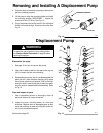
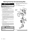
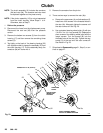
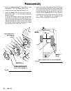
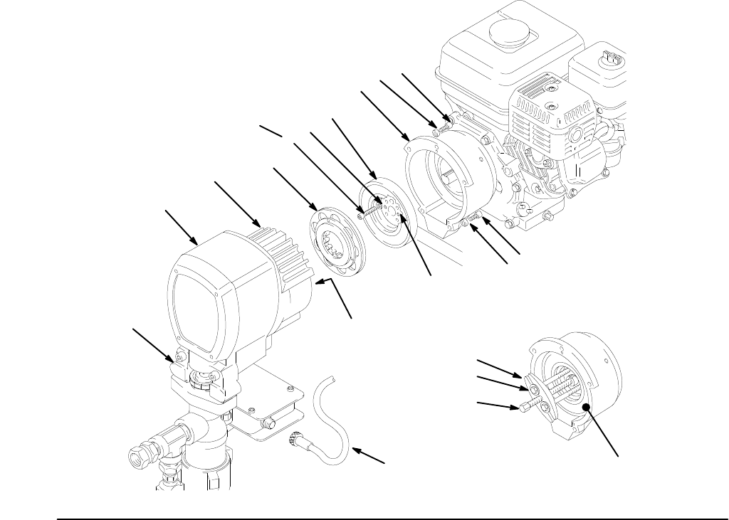
NOTE: The clutch assembly (9) includes the armature
(9b)
and rotor (9a). The armature and rotor must
be
replaced together so they wear evenly
.
NOTE: If the pinion assembly (19) is not yet separated
from the clutch housing, follow Steps 1 to 4.
Otherwise,
start at Step 5.
1.
Relieve the pressure.
2. Disconnect the hose from the displacement pump.
Disconnect the cord set (62) from the pressure
control.
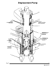
3. Remove the bottom two screws (3) from the clutch
housing (17) and then remove the remaining three
screws (3).
4. Tap lightly on the back of the bearing housing (23)
with
a plastic
mallet to loosen the assembly (D) from
the clutch housing (17). Pull the assembly away; the
armature
(9b) will come with it.
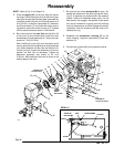
5.
Remove the armature from the pinion.
6.
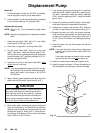
There are two ways to remove the rotor (9a):
a. Remove
the capscrews (4) and lockwashers (2).
Install
two of the screws in the threaded holes in
the
rotor (9a). Alternately tighten the screws until
the
rotor comes of
f. See Fig. 23.
b. Use
a
standard steering wheel puller (A) with two
1/4–28
x 3 or 4 in. long screws (B). Replace
the
short
screws of the steering wheel puller with the
longer screws. Turn the screws (B) into the
threaded
holes of the
rotor (9a). T
ighten the cap
-
screw (C) of the tool until the rotor comes off.
See
Detail in Fig. 23.
7. Skip
ahead to
Reassembly
,
page 31, Step 6, or con
-
tinue
on page 27.
THREADED
HOLES
A
B
C
D
TORQUE
T
O 7 ft–lb (9.5 N.m)
USE A STEERING WHEEL
PULLER T
O REMOVE ROT
OR
PINION SHAFT
INSIDE THIS
HOUSING
0402
23
9b
4
2
9a
17
2
3
2
3
62
19
Ref
9a
Fig. 23