


308813 7
Installation
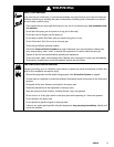
Manifolds 241161 and 241162
6. In a circulating system, connect an electrically
conductive fluid hose to the gun fluid outlet (G).
In a non-circulating system, remove the gun
fluid outlet fitting (G) and plug the outlet port with
the pipe plug (109) supplied.
8576A
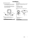
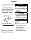
Fig. 4: Manifolds 241161 and 241162
C
F (or G)
KEY
C Cylinder Air Inlet: accepts 1/4 in. (6.3 mm) O.D. tubing
F Fluid Inlet: 1/4–18 nptf or #5 JIC (1/2–20 unf)
G Fluid Outlet (circulating gun only): 1/4–18 nptf or #5 JIC
(1/2–20 unf)
G (or F)
FAN
CYL
ATOM
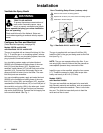
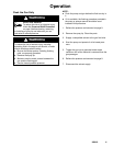
Manifold 244930
This manifold is equipped with passages for circulating
water to maintain the temperature of the gun. Ports
provided are:
D Side water inlet, 1/4 npt(f)
D Top water outlets, 1/8 npt(f)
D Side RTD sensor, 1/8 npt(f)
See Accessories, page 27, for available fittings and
sensors.
TI1397A
TI1397A
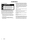
Fig. 5: Manifold 244930
KEY
L Water Outlet: 1/8 npt(f)
M Air Inlet (to open valve): 1/8 npt(f)
N Fluid Inlet: 3/8(f)
P Water Inlet: 1/4 npt(f)
L
M
L
N
P