


3 310584D
T1-TITANIUM NON-HVLP SPRAY GUN
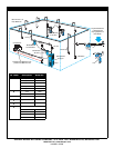
Setup
• Check that your shop air provides adequate air flow.
• Use a minimum 5/16 in. ID air supply hose.
• Set air and fluid pressure regulator according to paint man-
ufacturer’s recommendation for conventional equipment. Do
not exceed 100 psi (0.7 MPa, 7 bar).
• Make sure no air restrictions, such as low-volume cheater-
valves, obstruct the air flow. If an air adjusting valve is
desired, use a SHARPE Air Adjusting Valve 24AAV (part
no. 2210), 36AAV-HOV (part no. 3310) or HOV (part no.
U04410).
• Install a shutoff valve (not supplied) downstream of the air
regulator to shut off gun air.
• Install a shutoff valve (not supplied) on the fluid supply line
to shut off fluid to the gun.
• Install an inline air filter (not supplied) to clean and dry the
air supply to the gun.
1. Connect a clean, dry, filtered air supply to gun air inlet (9).
2. Connect fluid supply line to the gun fluid inlet (38).
If this is first time using the equipment, flush the spray gun.
3.
Operation
Pressure Relief Procedure
1. Turn off gun air and fluid supply.
2. Trigger the gun to relieve pressure.
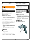
Flushing
Flush before using the equipment, before changing colors, and
when you are done spraying. Use solvent that is compatible with
gun wetted parts and fluid that will be sprayed. Flush at lowest
possible pressure.
1. Follow Pressure Relief Procedure.
2. Connect a solvent supply line to the gun fluid inlet (38).
3. Spray into grounded metal waste container until equipment
is clean.
4. Follow Pressure Relief Procedure.
Spraying
1. Connect the fluid supply line to the gun fluid inlet (38).
2. Turn on shop air to gun and set atomizing pressure with the
gun fully triggered.
3. Adjust the pattern size and shape with the spray width
adjustment knob (17d). Turn knob clockwise to reduce pat-
tern size and counterclockwise to increase it.
4. Fluid control knob (16) is factory set for maximum needle
trigger travel and material flow. To decrease needle/trigger
travel and decrease fluid flow, turn the knob clockwise.
5. Adjust fluid pressure regulator until desired fluid flow rate is
reached.
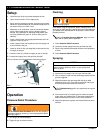
FIG. 1
WARNING
Follow Pressure Relief Procedure when you stop spraying
and before cleaning, checking, or servicing equipment. Read
warnings, page 2.
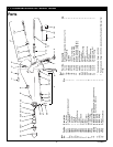
17d
38
6
16
9
WARNING
Read warnings, page 2.
Refer to Compliant Cleaning Methods, page 4, to com-
ply with air quality laws if applicable.
CAUTION
Excessive atomizing air pressure can increase over-spray,
reduce transfer efficiency, result in a poor quality finish
from dry spray.
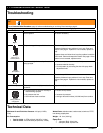
See Troubleshooting guide if you experience an irregular
pattern.