Control Board Replacement
22 311911C
FinishPro 395
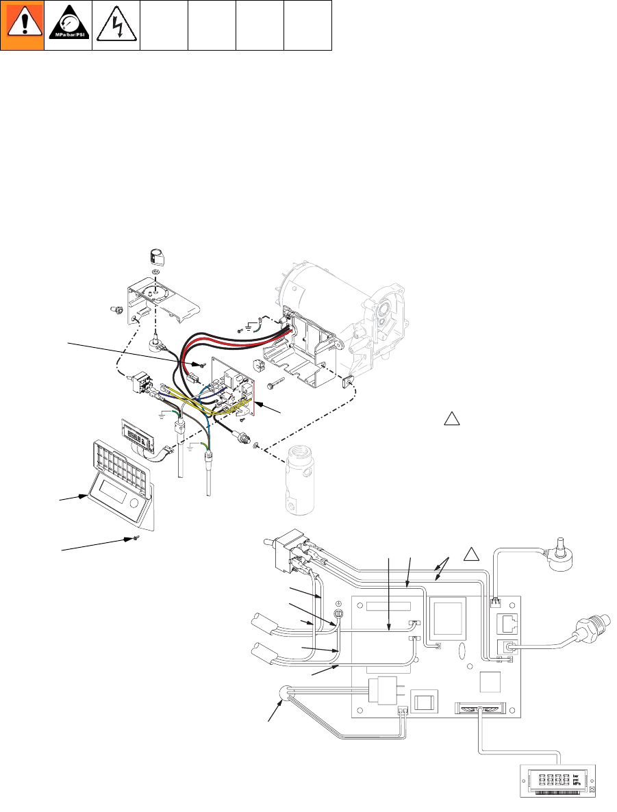
See Wiring Diagram, page 36.
Removal
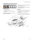
1. Relieve pressure, page 7. Disconnect power cord
from outlet.
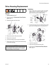
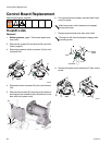
2. Remove four screws (12) and cover (50).
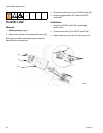
3. Disconnect all leads to motor control board (49).
4. Remove screws (6) and motor control board.
Installation
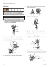
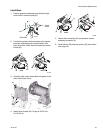
1. Clean pad on rear of motor control board (49). Apply
small amount of thermal compound to pad.
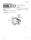
2. Install motor control board with screws (6).
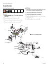
3. Connect all leads to motor control board.
4. Bundle and tie all loose wires so none are in contact
with inductor coil.
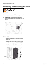
5. Install cover (50) with four screws (6).
To Compressor
Yellow
White
Black
Green
Brown
Green/Yellow
Black
Black
To Power Plug
From Motor
ON/OFF
Switch
Digital Display
Transducer
Potentiometer
BlackBlue
2X White
Red (+)
Black /
White (-)
50
12
6
49
ti9715a
1
1
Yellow wires not used on 240V


