


G0505 12
1
⁄2" Lean & Mean Portable Planer
-20-
SECTION 8: SERVICE ADJUSTMENTS
Disconnect power from
the machine when per-
forming any service
adjustments. Failure to
do this may result in seri-
ous personal injury.
!
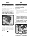
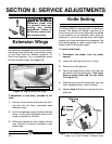
Figure 14. Aligning extension wings.
Extension Wings
Your planer is equipped with front and rear exten-
sion wings. Each wing folds up for machine mobil-
ity and folds down for machine operation. To
check the alignment, lay a straightedge across
the bed and both wings. See Figure 14.
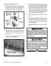
If adjustment is necessary, proceed as fol-
lows:
1. Use the 10mm wrench and loosen the lock-
ing nuts and set bolts underneath each
extension wing.
2. Hold a straightedge across the bed and both
wings, and turn the adjustment bolts so the
wings are parallel to the table.
3. Without turning the set bolts, tighten the lock
nuts. Recheck to ensure consistency from
side-to-side.
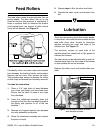
Adjustment Bolt and Locknut
Figure 15. Turn tightening bolt clockwise to loosen.
Knife Setting
The Model G0505 is equipped with a 2 blade cut-
terhead. The blades are locked in position by a
knife locking bar with seven bolts that are angled
to put pressure on the assembly when they are
tightened. A set of two springs under each blade
pushes up to keep the blade portion exposed. The
knife setting gauge is used to push down on the
blade to set it to the proper height.
To remove the knives:
1. Disconnect the planer from the power
source!
2. Lower the cutterhead as far as it will go.
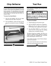
3. Remove the chip deflector.
4. Use the provided 8mm wrench to loosen the
gib bolts in the knife locking bar. Turn clock-
wise to loosen bolts and free the knife!
(See Figure 15)
5. Slide the knife out of the cutterhead. Use care
when handling knives—they are sharp!
6. Repeat steps 3-4 above to remove the sec-
ond knife.