


G0637/G0638 Cyclone Dust Collector
-33-
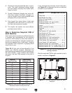
Calculating Duct Resistance
Adding duct work, elbows, branches and any
other components to a duct line increases airflow
resistance (static pressure loss). This resistance
can be minimized by using rigid (smooth) pipe
and gradual curves, as opposed to flexible pipe
and 90˚ elbows.
To help you think about this resistance, imagine
riding a bicycle in a tunnel that is an exact replica
of your duct work. If the inside of the tunnel is very
bumpy (flexible pipe) and has many sharp turns
(90˚ elbows), it will take a lot more effort for you to
travel from one end to the other than if your path
had been smooth and straight.
The purpose of calculating this resistance is to
determine if it is low enough from the machine to
the dust collector to meet the given requirement
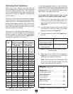
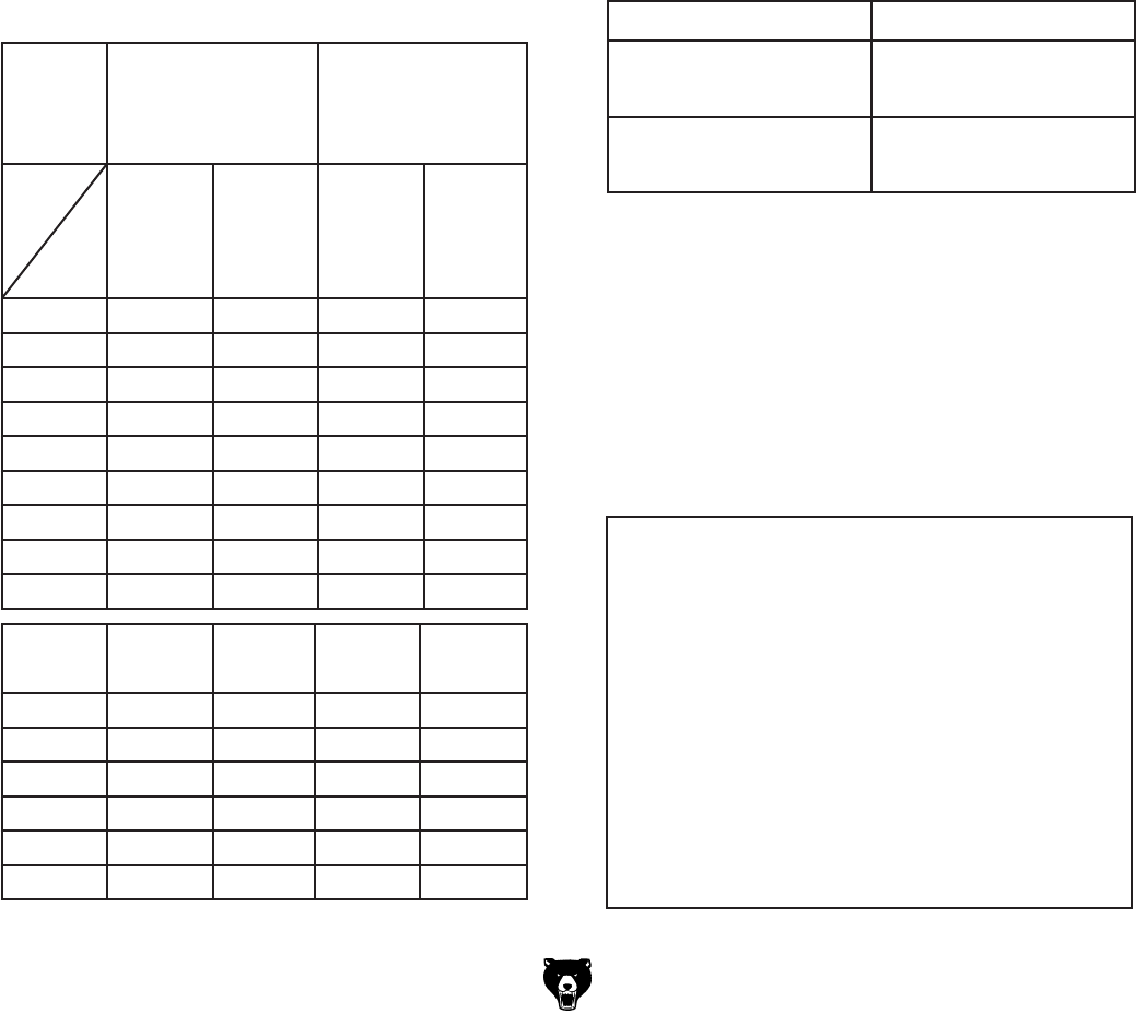
for the machine. Use the charts in Figure 55 to
calculate the resistance of duct work.
Fitting
Dia.
90˚
Elbow
45˚
Elbow
45˚
Wye(Y)
90˚
Wye(Y)
3" 0.47 0.235 0.282 0.188
4" 0.45 0.225 0.375 0.225
5" 0.531 0.266 0.354 0.236
6" 0.564 0.282 0.329 0.235
7" 0.468 0.234 0.324 0.216
8" 0.405 0.203 0.297 0.189
Duct
Dia.
Approximate
Static Pressure
Loss Per Foot of
Rigid Pipe
Approximate
Static Pressure
Loss Per Foot
of Flex Pipe
Main
Lines
at 3500
FPM
Branch
Lines
at 4000
FPM
Main
Lines
at 3500
FPM
Branch
Lines
at 4000
FPM
2" 0.091 0.122 0.35 0.453
2.5" 0.08 0.107 0.306 0.397
3" 0.071 0.094 0.271 0.352
4" 0.057 0.075 0.215 0.28
5" 0.046 0.059 0.172 0.225
6" 0.037 0.047 0.136 0.18
7" 0.029 0.036 0.106 0.141
8" 0.023 0.027 0.08 0.108
9" 0.017 0.019 0.057 0.079
Figure 55. Static pressure loss charts.
Additional Factors Static Pressure Loss
Seasoned (well used)
Dust Collection Filter
1
Entry Loss at Large
Machine Hood
2
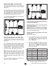
In most small/medium shops it is only necessary
to calculate FPM for the line with the longest duct
length or the most fittings (operating under the
assumption that if the line with the highest resis
-
tance works, the others will be fine).
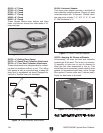
To calculate the static pressure loss of any
given line in the system, follow these steps:
1. Make a list of each size duct in the line,
including the length, and multiply those num
-
bers by the static pressure loss value given in
Figure 55.
2. List each type of elbow or branch and multiply
the quantity (if more than one) by the static
pressure loss given in
Figure 55.
3. Add the additional factors from Figure 56 to
your list.
Figure 56. Additional factors affecting static
pressure loss.
4. Total your list as shown in the example in
Figure 57 to come up with your overall static
pressure loss number for that line.
Note: Always account for a seasoned filter,
so you don't end up with a system that only
works right when the filter is clean.
Figure 57. Example list for totaling SP loss.