"+%"
<%+,)&'Ha^Y^c\IVWaZHVl
READ ELECTRICAL SAFETY
ON PAGE 56!
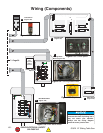
Wiring (Components)
(
)
+
*
V
&'
)(
&'
&
'
)(
&'
)
)
*
*
&
&
&
&
'
'
'
'
+
+
(
(
&'
&
*
'
(
)
'&
'%
J&
K&
L&
HiVgi
8VeVX^idg
&+B;9
)*%K68
O'
J&
J'
I&
I'
&
&
'
'
(
)
O&
Y
,
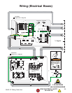
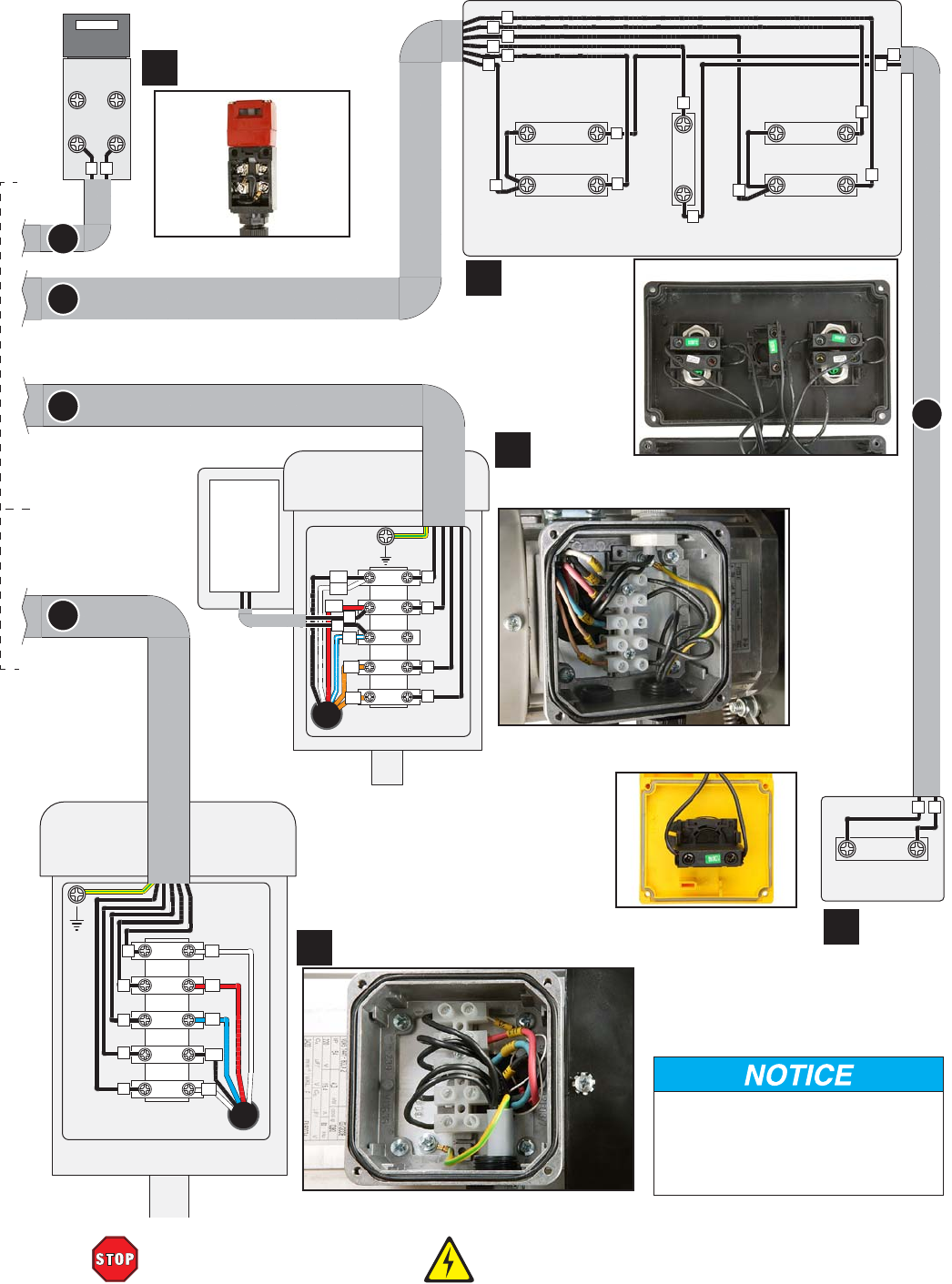
The motor wiring shown here is
current at the time of printing, but it
may not match your machine.
Always use the wiring diagram
inside the motor junction box.
X
W
[
&'
IdB6>CBDIDGIdH8DG>C<BDIDG
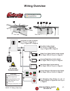
Limit Switch
Figure 102
Control Panel
Figure 103
Stop Switch
Figure 105
Scoring Blade
MotorFigure 104
Main Blade Motor
Figure 106
Figure 105. Hidehl^iX]#
Figure 102. A^b^iHl^iX]#
Figure 103. 8dcigdaeVcZa#
Figure 104. HXdg^c\WaVYZbdidg#
Figure 106. BV^cWaVYZbdidg#
Id Page 59


