


-16-
G0500/G1018/G1018HW 8" Jointers
4. Place the cover back on the switch and
secure it to the switch body with the two plas-
tic screws.
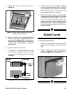
5. Locate the shortest length cord (motor cord)
and close a grommet around the wire, so the
larger end of the grommet is toward the
switch.
6. Thread the motor cord through the access
hole in the stand, which is located just below
the switch.
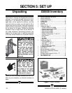
This section will cover the minimum assembly
and adjustment instructions needed to begin
operation. For best results, complete the assem-
bly in the order provided in this manual and then
read the remaining portion of the manual before
attempting any type of operations.
Safety must come first! Read and follow these
instructions before beginning assembly:
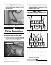
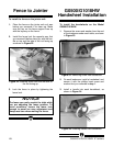
Switch Installation
To install the switch:
1. Locate the #10-24 x 1
1
⁄2" Phillips head
screws that are included in the hardware bag
with the switch.
2. Remove the switch cover by unthreading the
two plastic screws from the front of the
switch.
3. Position the switch over the holes and secure
it to the stand with the #10-24 x 1
1
⁄2" Phillips
head screws, as shown Figure 11.
Figure 11. Fastening switch to stand.
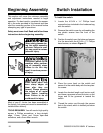
Beginning Assembly
Most of your 8'' Jointer has been assembled at
the factory, but some parts must be assembled or
installed after delivery.
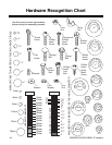
TOOLS REQUIRED: You will need a high quality
square, a Phillips screwdriver, a long straight-
edge, 10mm, 12mm and 14mm open-end
wrenches, and a 3mm Allen wrench.
Some metal parts may
have sharp edges on
them after they are
formed. Please examine
the edges of all metal
parts before handling
them. Failure to do so
could result in injury.
Disconnect power to the
machine when perform-
ing all assembly steps.
Failure to do this may
result in serious person-
al injury.
Wear safety glasses dur-
ing the entire assembly
process. Failure to com-
ply may result in serious
personal injury.