


-22-
G0500/G1018/G1018HW 8" Jointers
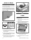
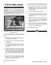
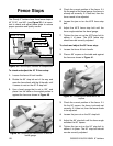
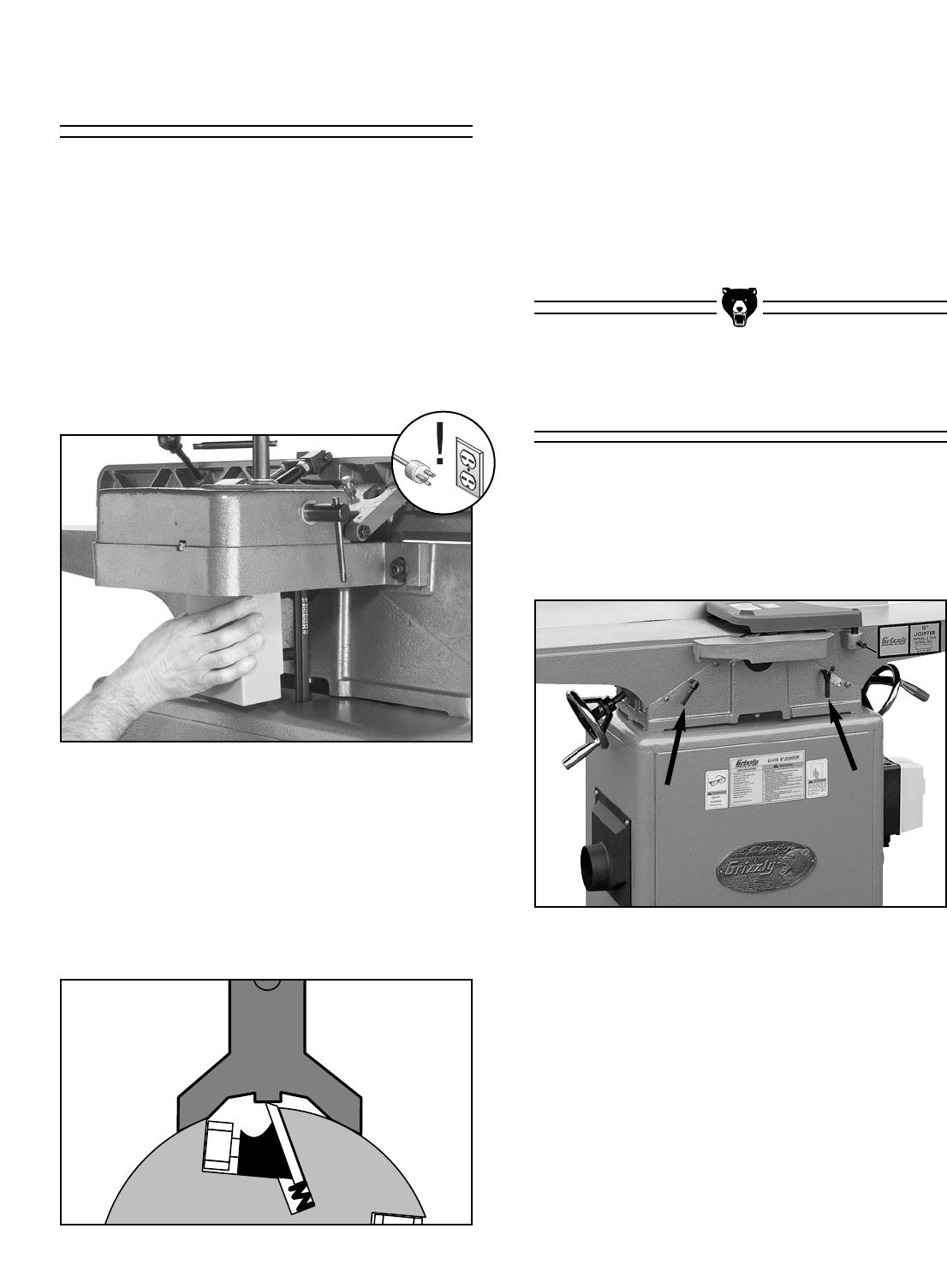
Figure 29. Jointer.
Both tables can be adjusted by unlocking the
table locks (see Figure 29) and rotating the hand-
wheels. To accurately joint or plane a piece of
stock, both tables must be aligned correctly,
beginning with the outfeed table.
Table Alignment
The knives were set to their proper height at the
factory, but we recommend that you inspect them
to ensure proper operation and table setup.
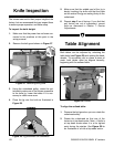
To inspect the knife height:
1. Make sure that the power has not been con-
nected to the machine at this point in the
setup process!
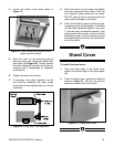
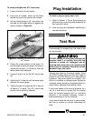
2. Remove the belt guard shown in Figure 27.
Knife Inspection
Figure 27. Removing belt guard.
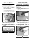
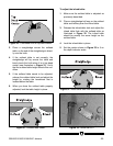
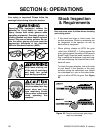
Figure 28. Jig placement on cutterhead.
3. Using the cutterhead pulley, rotate the cut-
terhead to make one of the knives accessible
to the knife jig. Lower the tables if it is nec-
essary to make more room.
4. Place the jig over the knife as illustrated in
Figure 28.
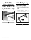
5. Make sure that the middle pad of the jig is
barely touching the knife and that the pads
on the ends of the jig are resting firmly on the
cutterhead.
6. Repeat step 5 on all knives. If you find that
any knives are out of adjustment, correct
them as discussed in Section 7: Service
Adjustments.
To align the outfeed table:
1. Remove the belt guard so you can rotate the
cutterhead safely.
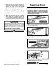
2. Rotate the cutterhead so that one of the
knives is at top dead center. Note—A knife is
at top dead center when it is at its highest
point during the rotation. See Figure 30 for
an illustration of a knife at top dead center.