G1183/1276 Combination Sander -15-
Belt Installation
Belt Tracking
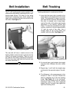
The 6'' x 48'' sanding belt is easily installed. First
remove the belt guard by loosening the four com-
bination-head screws. Pull down on the spring
loaded belt tensioning lever which lowers the
upper roller and allows the belt to be slid off of the
two rollers. See Figure 14.
2. You should see a gap between the straight
edge and roller. Measure this with a feeler
gauge.
3. Repeat step 1 and 2 with the straight edge
positioned at the opposite edge of the plat-
en.
4. The difference in the measurements is the
amount of "twist" in the belt. Reduce the
twist by adjusting one of the two tracking
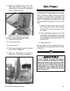
knobs. See Figure 16. If the "out-board"
end (or the end furthest from the tracking
adjustment side) of the roller measures
greater than the "in-board" side, tighten the
right hand tracking knob.
Tracking adjustment is conducted as follows:
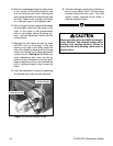
1. Insure that the upper roller is parallel to the
platen (there is no adjustment for the lower
roller). This adjustment is easier to accom-
plish with the belt removed. Remember that
the roller is crowned, and a rough align-
ment of the roller to the platen was already
described in the section entitled Belt
Platen. To determine parallelism for proper
tracking, measure at a point approximately
.5'' from the ends of the roller. Use a
straight edge on top of the platen and
extend it over the roller. See Figure 15.
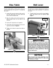
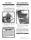
Figure 14. Installing sanding belt.
The new belt will have a rotation arrow on the
backing. Make certain the belt is placed onto the
rollers in the proper orientation. There is a rota-
tion label on the housing indicating the direction.
Pull the lever down and slide the new belt onto
the rollers and center it.
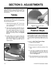
Figure 15. Measuring platen to roller parallelism.


