


G7945/46 Radial Drill Press -11-
The headstock repre-
sents a heavy load. Seek
assistance before begin-
ning this step.
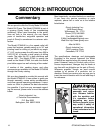
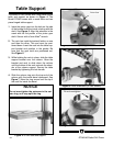
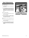
Figure 8.
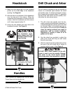
Lock Handles and gib location.
1. Make sure the locking gib is in the recessed
pocket on the inside edge of the headstock
opening. See Figure 8.
2. With the help of an assistant, lift the headstock
over the top end of the column. When the
underside of the headstock is lined up with the
column, slide the headstock onto the column
until it stops (approximately 2").
3. Screw two lock handles into each side of the
headstock bracket. See Figure 8.
Headstock
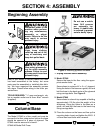
Three handles are supplied with the drill press.
Thread them into the handle hub.
Handles
The drill chuck is attached to the drill spindle by
means of a machined taper between the chuck
and spindle nose. An almost permanent assem-
bly is created when properly joined. To assemble
the drill chuck and mount it to the spindle, care-
fully follow the instructions below:
1. The drill chuck and spindle must be thor-
oughly cleaned and dried before assembly. It
is recommended that mineral spirits be used
for this task. Refer to the safety warnings on
the container of the mineral spirits. Failure to
clean the mating surfaces may result in
separation, and an unsafe condition.
Separation is usually a result of oil or
grease on the taper.
2. Use the chuck key provided to adjust the
jaws of the chuck until they are well inside
the drill chuck body.
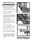
3. Slide the chuck onto the spindle end and tap
the end of the drill chuck with a rubber or
wooden mallet to seat it. See
Figure 9.
Drill Chuck and Arbor
DO NOT use a steel hammer on the drill
chuck to seat it onto the spindle. Damage
will occur to the chuck and/or spindle
which may make them unusable or unsafe.
Figure 9.
Seating chuck into spindle. (Note
retracted jaws.)
Locking gib is located inside
the headstock in this location.