-34- Ultimate Series Jointers
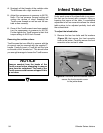
4. Sparingly oil the threads of the carbide cutter
Torx® screws with a light machine oil.
5. Adjust the compressor air pressure to 30 PSI.
Note—The low pressure (torque) setting will
reduce the chance of cross threading the
Torx® screw threads as well as seat the car-
bide cutters correctly.
6. Once all the Torx® screws have been seated,
turn the compressor air pressure to 85 PSI.
Further tighten the Torx® screws to their final
torque setting of 48-50 Inch-Pounds.
Removing the carbide cutters:
Torx® screws that are difficult to remove with the
air wrench can be removed with the supplied T-
handle. Carefully insert a Torx® bit into the hole
on the side of the “cheater bar.” This should allow
you enough leverage to loosen the Torx® screws.
Infeed Table Cam
Under each corner of the infeed table is an eccen-
tric that can be turned with a wrench—lifting or
lowering that corner of the table. A coordinated
adjustment of all four eccentrics allows the infeed
table surface to be adjusted perfectly level with
the outfeed table.
To adjust the infeed table:
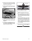
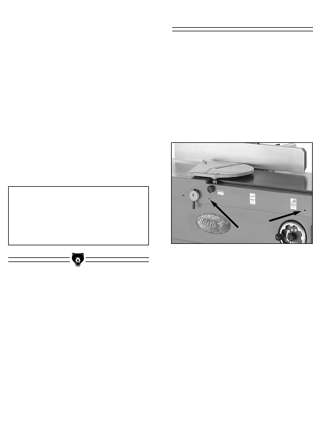
1. Remove the four hex bolts and flat washers
(Figure 38) that secure the front eccentric
cover to the jointer. Carefully remove the front
eccentric cover and set it aside.
Figure 38. Hex bolts and flat washers used to
secure the front eccentric cover
to the jointer base.
NOTICE
Remove sawdust from the heads of the
Torx® screws before attempting to remove
them from the cutterhead. The head of the
Torx® screws could become stripped if this
is not done.


