


-12-
Model G9986 8" Drill Press
Test Run
Wear safety glasses
whenever starting or
using machine. Failure
to comply may result in
serious personal injury.
Keep loose clothing
rolled up and out of the
way of machinery and
keep hair pulled back.
Once assembly is complete, you understand the
safety instructions, and the work area is cleared
of all tools, you are ready to test run the drill press
and test the switch disabling key to make sure
they function properly.
To test run the drill press:
1. Connect the drill press to the power source.
2. Pull up on the switch to turn the drill press
ON. The drill press should run smoothly, with
little or no vibration or rubbing noises.
If you notice anything unsual about the drill
press operation, turn if OFF and investigate
and correct the issue before operating the
machine further. If you cannot easily locate
the source of a potential problem, refer to
Troubleshooting on Page 19 or contact our
Technical Support at (570) 546-9663.
3. Remove the switch key (yellow portion of the
main switch), and try to turn the switch
ON.
— If the drill press does NOT turn
ON with
the key removed, then the safety feature
is working as intended.
— If the drill press turns
ON with the key
removed, then the safety feature is mal-
functioning. Contact Tech Support imme-
diately.
Mounting
Once you have confirmed that your machine is
running properly, mount it to a workbench, using
the holes in the base as a guide.
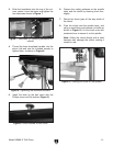
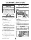
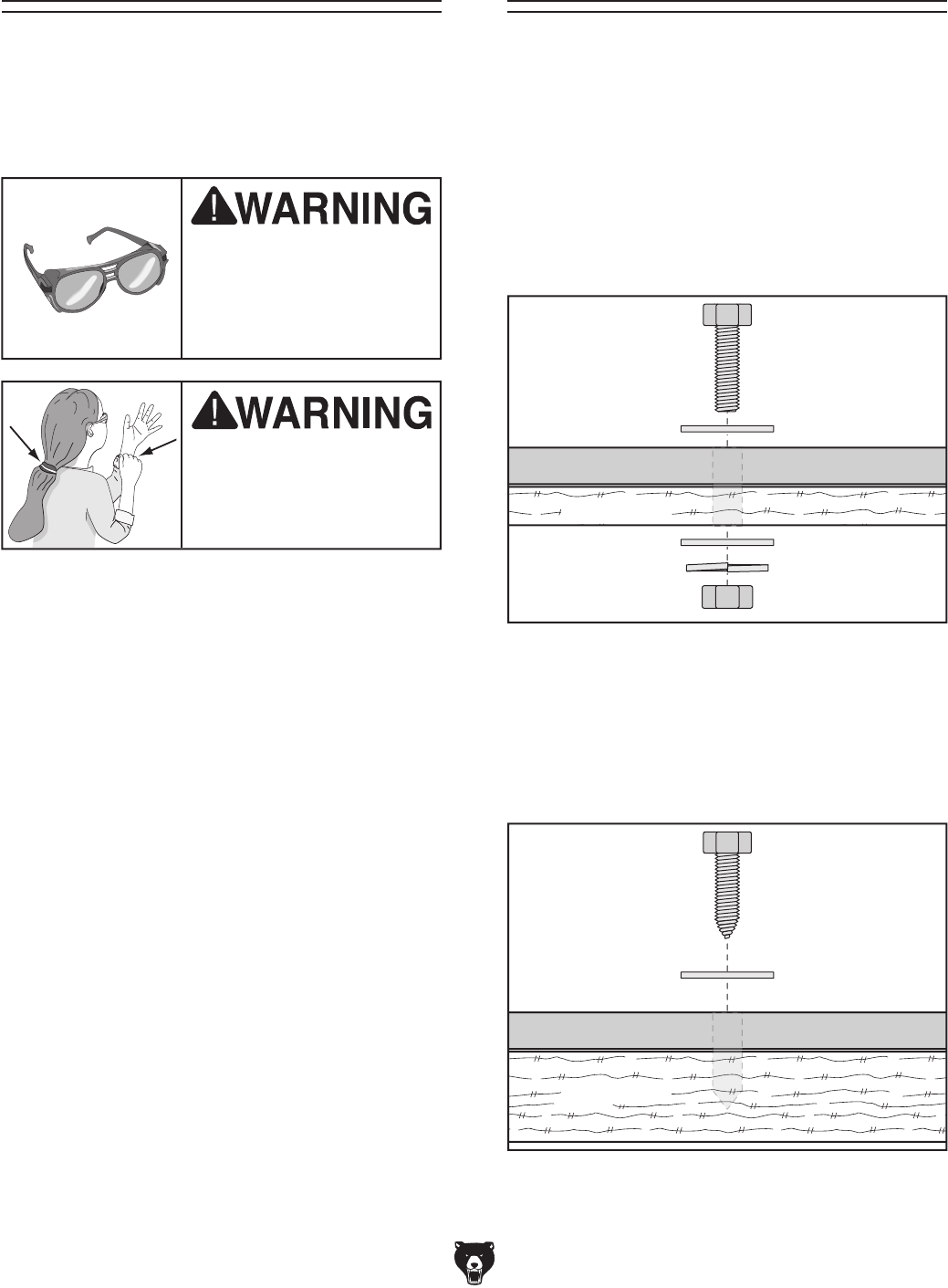
The strongest mounting option is a "Through
Mount" where holes are drilled all the way
through the workbench, and hex bolts, washers,
and hex nuts are used to secure the drill press to
the workbench. Refer to the illustration in
Figure
11 for details about this option.
Figure 11. Example of a through mount setup.
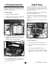
Figure 12. Example of a direct mount setup.
Another option for mounting is a "Direct Mount"
where the machine is simply secured to the
workbench with a lag screw and washer. Refer to
the illustration in Figure 12 for details about this
option.