


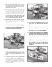
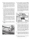
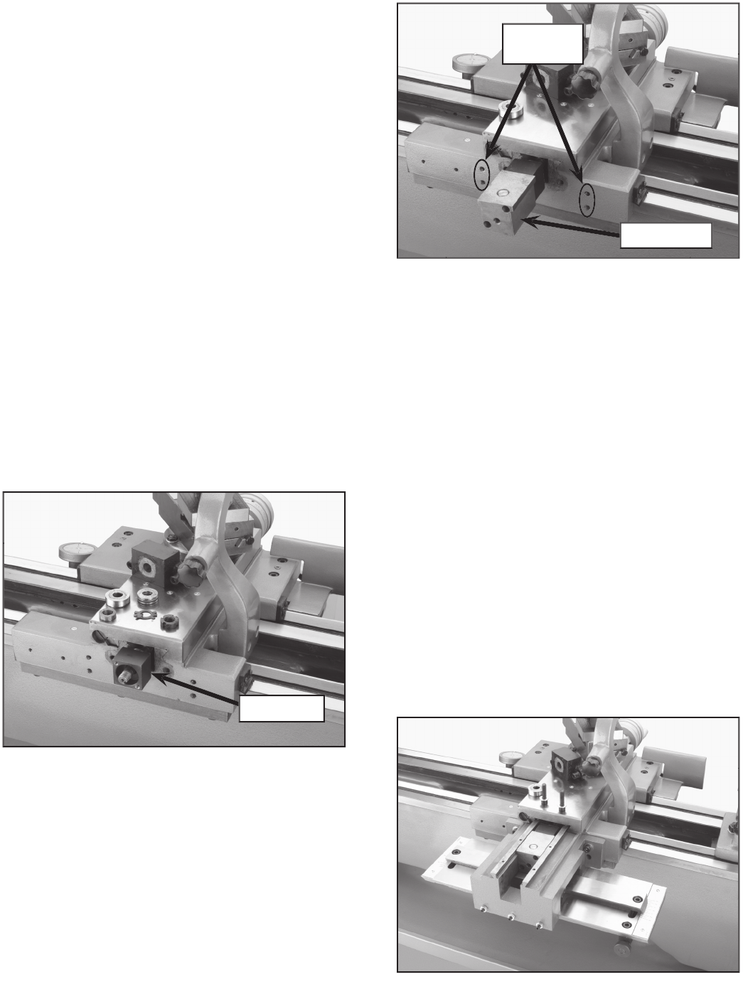
Figure 5.
Slide Block Assembly.
6.
Remove the 6 philips head screws from the
top cover plate of the main body. Set the
screws and cover aside for later use in reas-
sembling the main body.
7.
Remove the end block and slide block from
the main body by pulling up. These two
blocks are attached by two cap screws.
T
hey
are located in the opening you just uncovered
in
Step 6
.
The slide block is loosely pinned to
a portion of the slide. Be careful not to lose
the pin. Either set it aside for future installa-
tion or be sure to keep the pin in place.
8.
Separate the end block and slide block by
loosening the 2 cap screws in the slide block.
Set the slide block and cap screws aside for
s
tep 13
.
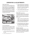
9.
Assemble the end block and bearing (
Figure
4
). The pocket for the bearing and the thread-
ed holes must be facing outwards when slid-
ing the end block onto the lead screw.
10.
Install the bearing, spacer, and star washer
in the same order they were removed. These
items will fit inside the opening in the end
block.
11.
Thread the nut onto the end of the lead screw
and hand tighten while holding the cross
slide handwheel. Do not over-tighten this nut.
To check, turn the end block. Only a small
amount of resistance should be felt. Adjust
the nut as needed.
Sl
ide
Block
12.
Hold the nut in place and bend one or more
tangs of the star washer to keep the nut in
place.
13.
Assemble the slide block to the end block
using the two cap screws that were already
in the slide block. The end block may need to
be rotated to line up the holes (
Figure 5
).
14.
There are four threaded holes (See
Figure 5
)
on the rear of the carriage used to mount the
main body to the lathe. Remove any paint or
debris from these holes before attemping to
mount the main body.
15.
Align the four holes in the main body with the
thread holes on the carriage. Use the four
M8 - 1.25 x 30 cap screws to loosely fasten
the main body to the lathe. A long-handled,
ball end hex wrench works best for this step
(
Figure 6
).
Threaded
Holes
Figure 4.
End block assembly.
End Block
Figure 6.
Main Body Assembly.