


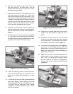
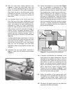
Figure 7.
Support Rod and Deadman Assembly.
16.
With the main body loosely fastened (see
Figure 6
), move the slide block back and
forth, by either pulling/pushing on the lead
screw or turning the cross slide handwheel.
Stop when the pin in the slide block can be
inserted into the hole in the slide. Push the
pin, refer to
s
tep 7
, into place to secure the
slide block.
17.
The dovetail ways of the cross slide must
clear the top of the taper attachement and
line up with the dovetails on the taper attach-
ment. The holes in the taper attachment are
oversized to allow for height adjustment.
Adjust for clearance and check that the cross
slide moves in and out, along its full range of
motion, without increased resistance. When
the slide moves unobstructed and smoothly,
tighten the four mounting screws.
Note—
If
you are o
nly able to use two of the holes after
s
tep 16
, you will need to use the two roll pins
tep 16, you will need to use the two roll pins tep 16
included
with the taper attachment. To do this
y
ou will need to drill holes through
you will need to drill holes throughy
the main
ou will need to drill holes through the main ou will need to drill holes through
body and into the c
arr
iage. Use a
arriage. Use a arr
#9 or a 5
mm drill bit.
Be sure not to drill any deeper
tha
n
5
/
5/5
8
/8/
" into the carriage. Once the holes
are drilled, clean out any debris and insert the
roll pins.
18.
Assemble the top cover plate, removed in
s
tep 6
, using the six philips head screws
(
Figure 7
).
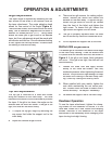
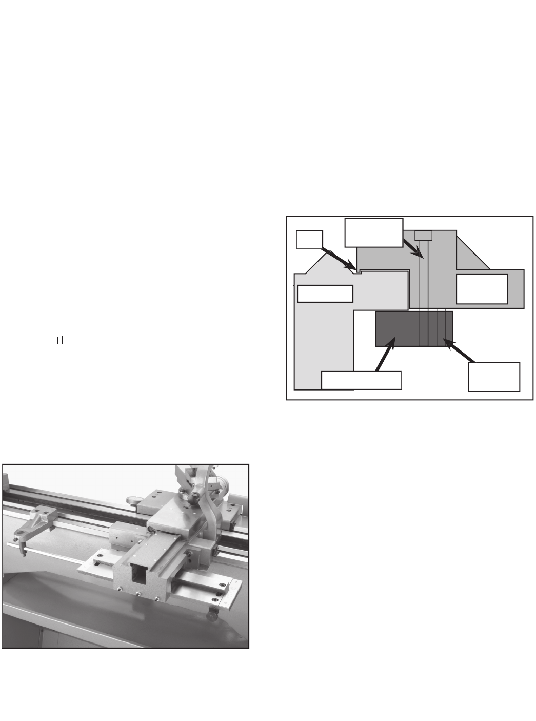
Figure 8.
Components of the deadman.
Bed Way
Clamping Jaw
Leveling
Screw
Solid
Bracket
Lip
Clamping
Screw
20.
A support rod attaches the deadman to the
main body of the taper attachment. The rod
attaches to the deadman by way of a hole in
the vertical shaft. Insert the rod into the hole
and secure in place by tightening the cap
screw. The vertical shaft is inserted into the
hole in the deadman and secured in position
with a cap screw. Loosen the cap screws.
Position the rod as shown in
Figure 7
and
secure the rod to the bottom of the main body
with the M6 cap screw provided.
21.
Adjust the position of the vertical shaft until
the support rod is parallel with the lathe bed.
Tighten the cap screws. Note—
Position the
deadman as close to the main body as pos-
sible for the best stability
.
sible for the best stability.sible for the best stability
22.
Re-attach the splash guard to the lathe and
reposition the lathe as needed.
19.
Attach the deadman to the lathe bed (
Figure
8).
The deadman is composed of a solid
cast bracket and a loose clamping jaw. The
bracket has two holes for screws that attach
the clamping jaw. It also has a lip that must
extend beyond the flat surface of the bed
way. The clamping jaw has two set screwst-
hat allow for adjustments. These set screws
should be adjusted until the clamping surfac-
es of the clamping jaw and bottom of the bed
way are parallel when the clamping screws
are tight. If these surfaces are not parallel,
loosen the clamping screws and adjust the
set screws as needed.