


H4519 3 HP Air Compressor
-9-
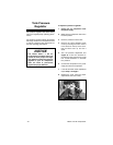
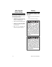
To control the air delivery to your tool:
1. Adjust the air control knob, shown in
Figure 6, to set the PSI that will be
delivered to your tool. Turn the knob
clockwise to increase the pressure
and counter-clockwise to decrease
the pressure.
Figure 6. Air control knob.
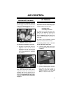
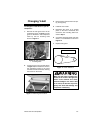
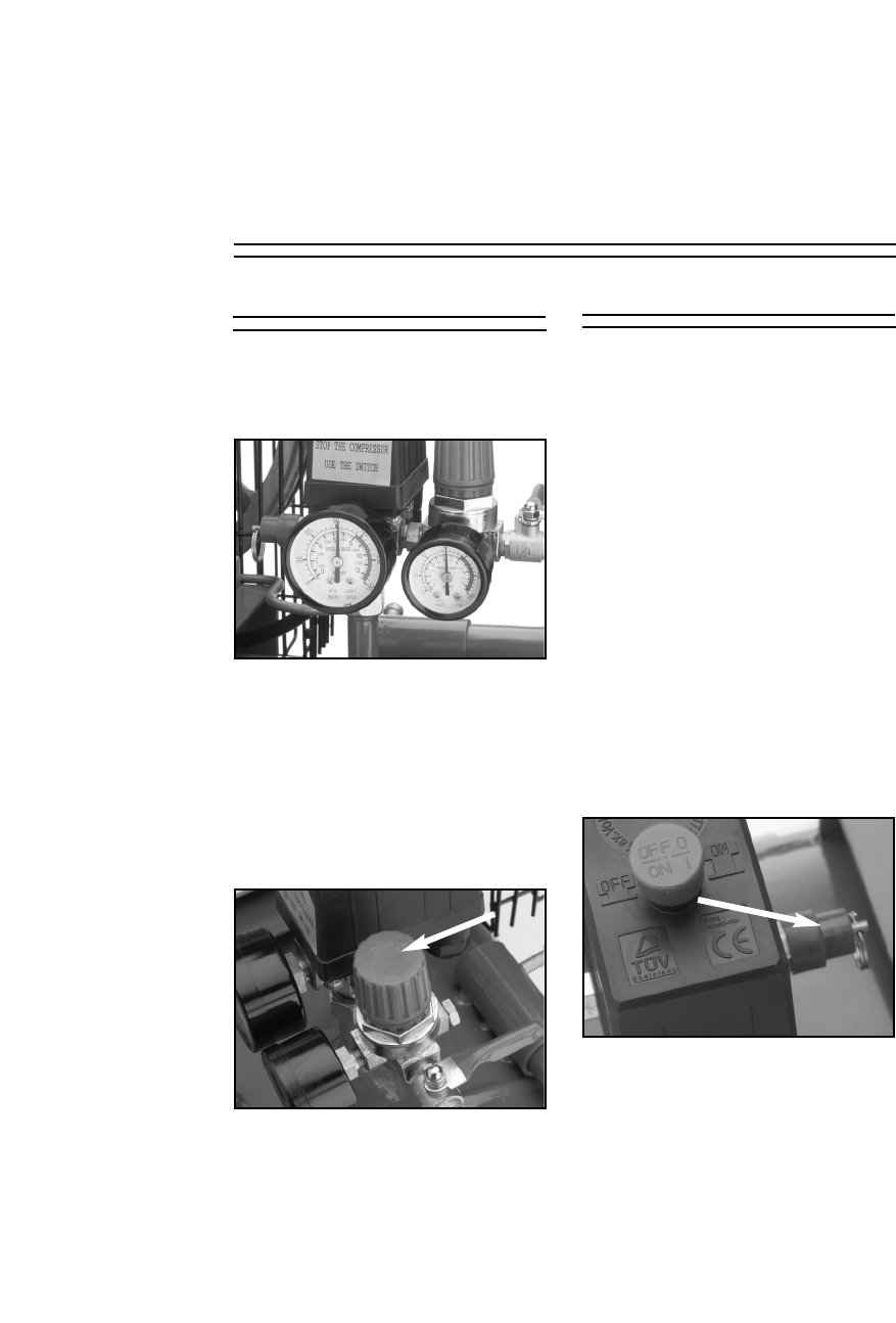
Figure 5. Pressure gauges.
The tank pressure is displayed on the left
pressure gauge, and the air to be delivered
to the tool is displayed on the right pres-
sure gauge shown in Figure 5.
AIR CONTROL
Delivered Pressure
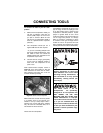
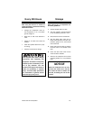
Figure 7. Safety drain valve.
There are two ways to release air from the
compressor tank other than through your
regulator and the use of air tools:
—The drain valve.
—The safety drain valve.
To release air by using the drain valve,
simply turn the release nut to allow air to
flow out of the tank. The drain valve is
shown in Figure 5. The drain valve is also
used to drain condensation that builds up
in the tank.
The safety valve automatically releases
pressure if the tank reaches 130 PSI.
To manually release the air in the tank
by using the safety drain valve:
1. Locate the safety drain valve on the
tank. The drain valve is shown below
in Figure 7.
Air Release
2. Pull the metal ring on top of the safe-
ty valve to bleed pressure from the
tank. Note—The ring is preset to
release air if the tank exceeds its
maximum pressure of 130 PSI. DO
NOT try to adjust the safety valve!
Note—The air tool that you attach to the air
compressor should have a preferred PSI
operating level. Set the pressure to be
delivered to the tool according to this pre-
ferred level. Understand the duty cycle
of the air compressor that is described
on page 7.