-8-
Some metal parts may have sharp edges
(called “flashing”) on them after they are
formed. Please examine the edges of all
parts before handling them. Failure to do so
could result in skin laceration.
SECTION 3: ASSEMBLY
Overview
Most of your Copy Attachment has been assem-
bled at the factory. However, you will need to
attach the handle to the carriage handwheel,
mount the longitudinal-feed handwheel and cut-
ting tool and mount the main assembly to your
lathe.
NOTICE
All assembly and adjustment instructions
assume that your lathe is axially aligned,
i.e., the headstock and tailstock are cen-
tered on the same axis. Consult your lathe
owner’s manual for proper procedure.
1.1.
4.
5.
6.
7.
8.
9.
10.
11.
12.
13.
14.
2.
3.
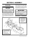
1. Copy Carriage Bed
2. Carriage Travel Cable
3. Cutting Tool Carriage
4. Cutting Tool Arbor
5. Mounting Brackets (2)
6. Carriage Stop
7. Longitudinal Handwheel
8. Master Spindle Support
9. Crossfeed Handwheel
10. Stylus Height Adjuster
11. Stylus
12. Quill Gap Adjuster
13. Template Support (2)
14. Spindle Support Adjuster
The illustration below indicates the features and
controls included with the Model G2891.
Assembly, adjustments, operation and mainte-
nance procedures will all be more successful
after you develop an understanding of the copy
attachment’s construction and functions.
G2891 Lathe Copy Attachment


