Installation
10 309463N
Wall Mount Packages
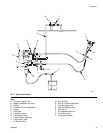
FIG. 2 illustrates a wall mount system.
1. Be sure the wall can support the weight of the
pump, bracket, hoses and accessories, as well as
the stress caused during operation.
2. Position the wall bracket (4) about 1.2-1.5 m (4-5 ft)
above the floor. For ease of operation and service,
make sure the pump air inlet, fluid inlet, and fluid
outlet ports are easily accessible.
3. Using the wall bracket (4) as a template, drill 9 mm
mounting holes in the wall. Wall mounting dimen-
sions are shown on page 27.
4. Attach the bracket to the wall. Use screws that are
long enough to keep the pump from vibrating during
operation. Be sure the bracket is level.
Air Inlet Fitting
The air inlet fitting (104) is held in place with a setscrew.
See page 22. Loosen this setscrew before removing the
fitting. Tighten the setscrew to hold the fitting in place.
Air Line Accessories
Install the following accessories in the order shown in
F
IG. 2, using adapters as necessary:
• A bleed-type master air valve (B) is required in your
system to relieve air trapped between it and the air
motor when the valve is closed. Be sure the bleed
valve is easily accessible from the pump.
• A pump air regulator (D) controls pump speed and
outlet pressure by adjusting the air pressure to the
pump. Locate the regulator close to the pump.
• A gun air regulator (N) controls air pressure to the
air-assisted spray gun.
• An air line filter (M) removes harmful dirt and mois-
ture from the compressed air supply.
• A second bleed-type air valve (L) isolates the air line
accessories for servicing. Locate upstream from all
other air line accessories.
Fluid Inlet Fitting
The packages include either a fluid inlet adapter (7) or
an elbow (8). These fittings include a sealing o-ring (7a,
8a). Be sure the o-ring is in place before installing the fit-
ting. Screw the fitting into the pump a minimum of two
full turns, until it faces the desired direction. It is not nec-
essary to fully engage the threads. Do not overtighten.
If your package uses the fluid inlet elbow (8), connect
the suction tube by pushing the tube into the elbow until
it seats, then tighten the elbow nut to secure the tube.
Suction Tube Strainer
To replace the suction tube stainer (9a), loosen the
clamp and remove the strainer. Slide the new clamp
onto the suction tube, install the new strainer, then slide
the clamp onto the strainer and squeeze it to tighten.
Fluid Line Accessories
Install the following accessories in the positions shown
in F
IG. 2, using adapters as necessary:
• A fluid filter (F) with a 60 mesh (250 micron) stain-
less steel element, to filter particles from the fluid as
it leaves the pump. Install a fluid drain valve (G),
which is required in your system to relieve fluid pres-
sure in the hose and gun.
• A fluid shutoff valve (H) shuts off fluid flow.
• A fluid pressure regulator (J) allows more precise
adjustment of the fluid pressure. See page 11.
• A gun or valve (T) dispenses the fluid. The gun
shown in F
IG. 2 is an air-assisted spray gun for light
to medium viscosity fluids.
• A fluid line swivel (S) allows easier gun movement.
• A suction kit (K) allows the pump to draw fluid from a
fluid container.
Flush the Pump Before First Use
The pump is tested with lightweight oil, which is left in to
protect the pump parts. If the fluid you are using may be
contaminated by the oil, flush it out with a compatible
solvent before using the pump. See Flush the Equip-
ment on page 14.


