


UNPACKING
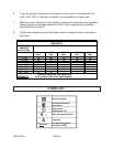
When unpacking, check to make sure all the parts shown on the Parts List on page 12
are included. If any parts are missing or broken, please call Harbor Freight Tools at the
number shown on the cover of this manual as soon as possible.
ASSEMBLY AND OPERATING INSTRUCTIONS
NOTE: For additional information regarding the parts listed in the following pages, refer
to the
Assembly Diagram on page 13.
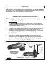
1. WARNING! Always make sure the Power Cord (part #50) of the Angle
Grinder is unplugged from its electrical outlet
prior
to adding any accessories or
making any adjustments to the tool.
SKU 03150 PAGE 10
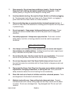
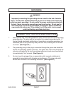
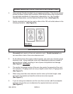
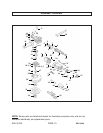
2. To install a 4-1/2” diameter Grinding Wheel (not included), depress the Stop Pin
(part #11) to keep the Spindle (part #27) from turning. Insert the Wrench
(part #58) into the two holes located in the Flange Nut (part #32). Unscrew and
remove the Flange Nut. Then, release pressure on the Stop Pin.
(See Figure D.)
3. Insert the 4-1/2” diameter Grinding Wheel fully onto the Spindle (part #27),
making sure the Grinding Wheel fits snugly against the inner Flange (part #30).
Depress the Stop Pin (part #11) to keep the Spindle (part #27) from turning.
Make sure the Flange Nut (part #32) is firmly retightened onto the Spindle.
Then, release pressure on the Stop Pin. (See Figure D.)
SPINDLE
(#27)
INSERT
4-1/2”
GRINDING
ONTO
WHEEL
FLANGE NUT (#32)
WRENCH (#58)
STOP PIN
(#11)
HANDLE
(#16)
BRUSH HOLDER (#40)
CARBON BRUSH (#41)
BRUSH CAP (#42)
FIGURE D
GEAR BOX
(#15)
POWER SWITCH (#39)
INNER FLANGE
(#30)