


Page 5SKU 34434 For technical questions, please call 1-800-444-3353.
UNPACKING
When unpacking, make sure the following accessories are included: blade adjustment gauge, “T”
wrench, screwdriver, dust collection outlet, push block and fence angle gauge.
INSTALLATION
1. The Jointer Planer should be installed permanently to a sturdy workbench for best results.
Each corner of the base should be xed securely to the surface by using bolts, nuts and washers.
2. If you wish your Jointer Planer to be portable, the following mounting instructions should be
followed. Use a solid piece of wood (not particle board) with a minimum thickness 3/4”. This
base must also be at least 36” L x 20”W. Bolt the Jointer Planer to the base with bolts, nuts and
washers. When using the machine, clamp it rmly to a stable and secure location for best results.
WARNING: CHECK BLADE SETTING AND TIGHTNESS BEFORE INITIAL USE.
ADJUSTMENTS & OPERATIONS
Cutting Depth Adjustment
CAUTION! Turn the machine off, unplug and wait until blades reach a complete stop before
adjusting the cutting depth!
1. To decrease the cutting depth, turn the depth control knob (67) clockwise; this will raise the
infeed table. To increase the cutting depth, turn the dial counter-clockwise.
CAUTION! Never adjust the cutting depth so that it exceeds 1/8”!
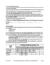
2. To check your cutting depth adjustment, rst put the depth adjustment gauge plate on the
outfeed table and allow it to hang over the infeed table. Use a ruler with the proper graduations
and measure from the bottom of the gauge to the top of the outfeed table. This will indicate your
cutting depth.
Fence Adjustment:
1. To adjust, angle your fence angle (0
o
-45
o
), loosen both fence angle adjustment levers (52).
Adjust to desired angle to according to the scale and tighten both levers.
2. To adjust the position of the fence on the table, loosen both fence adjustment knobs (39).
Adjust to desired position and then tighten. This should be done when you desire only a certain
section of the board to be planed or jointed.
3. When you have completed adjusting the fence, be certain that the auxiliary blade guard (45) is
over the cutter head assembly.
Replacing and Adjusting Blade:
CAUTION! Turn the machine off, unplug and wait until blades reach a complete stop before
adjusting the cutting depth!
NOTE: Both blades must be replaced simultaneously or else the balance will be affected.
1. Loosen the two screws (54) holding the belt cover (29) on and remove it.
2. To x the cutter head assembly (58) in place, pull the “U” shaped lock pin (36) out and
reposition it in the upper hole on the back of the machine. (See associated label on the back of
the Jointer Planer.) Rotate the drive belt (28) by hand until assembly “clicks” into place. A small
hole is provided in the pulley (73), which will accept a probe for easier turning.
REV 12/06