


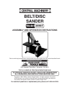

Page 7SKU 34951
For technical questions, please call 1-800-444-3353.
ASSEMBLY
The Belt Sander is shipped almost completely assembled. The major items to be at-
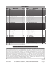
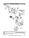
tached are the disc table (58), the belt table (31), and the sanding belt (6). (These numbers
refer to the assembly diagram and parts list at the back of this manual.) We will refer to the
tall part of the sander angled toward you as the front. The “on/off” switch is to your right.
Belt Table Assembly
Get out the table (31), 16mm screw (36), No. 8 washer (2), locking nut (32), knob
(33), spring (34), and screw (36).
Remove the cover (3) by removing the securing knob (1) and lifting up.
The screw (36) goes on the inside; the other pieces are installed from the outside.
The washer goes closer to the table, then the locking nut, followed by the knob,
spring, and finally the last screw.
The knob is used to lock the table in place when adjusting the angle.
Do not replace the cover until the belt has been installed. This is covered below.
Disc Assembly
Remove the cover (50).
Remove the dust collector (59).
Stick the sanding disc on the disc wheel (53).
Get the disc wheel to the shaft of the motor with the hex head bolt (52).
Replace the cover and dust collector.
Disc Table Assembly
Get out the table (58),4 x 22 pins (60), the No. 6 washers (55), and the wing nuts
(61).
Attach the table to the cover using the wing nuts and washers.
Drive in the pins so that the table can “swing” for tilting.
Miter Gauge Assembly
Get out the shaft (57), scale (56), No. 6 washer (55), and fastening knob (54).
Attach scale to shaft with washer and knob.
1.
2.
3.
4.
5.
1.
2.
3.
4.
5.
1.
2.
3.
1.
2.