


SKU 35149 For technical questions please call 1-800-444-3353. Page 10
Operation
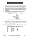
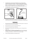
1. To turn on the Clamp Light, plug the Power Cord into the nearest 120 volt, grounded,
electrical outlet. Then, press the On/Off Switch located on the back of the Clamp Light.
WARNING! Always point the light away from the wall, whether the unit is in use or
not. If the unit is accidentally pointed at the wall while turned on or still hot after turned off, a
fire may result.
2. To turn off the Halogen Light, press the On/Off Switch located on the back of the Light.
Then, unplug the Power Cord/Plug from its electrical outlet.
Inspection, Maintenance and Cleaning
1. Always unplug the Halogen Lamp from its electrical outlet and allow the unit to completely
cool down before performing any inspection, maintenance, or cleaning.
2. Before each use: Inspect the general condition of the Halogen Lamp. Check for
misalignment or binding of moving parts, cracked or broken parts, damaged Power Cord,
damaged Grid, Lens and any other condition that may affect its safe operation. If a problem
occurs with the Clamp Light, have the problem corrected before further use. Do not use
damaged equipment.
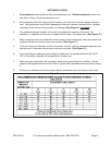
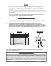
Parts List
Part Description Q’ty
1 6” Spring Clamp 1
2 Handle 1
3 Knob 2
4 Flat Washer 2
5 Phillips Head Bolt 3
6 Halogen Bulb 1
7 Bracket 1
8 Wing Knob 1
9 Light Housing w/Cord 1
10 Grid 1
PLEASE READ THE FOLLOWING CAREFULLY
THE MANUFACTURER AND/OR DISTRIBUTOR HAS PROVIDED THE PARTS DIAGRAM IN THIS MANUAL AS A REFERENCE TOOL
ONLY. NEITHER THE MANUFACTURER NOR DISTRIBUTOR MAKES ANY REPRESENTATION OR WARRANTY OF ANY KIND TO
THE BUYER THAT HE OR SHE IS QUALIFIED TO MAKE ANY REPAIRS TO THE PRODUCT OR THAT HE OR SHE IS QUALIFIED
TO REPLACE ANY PARTS OF THE PRODUCT. IN FACT, THE MANUFACTURER AND/OR DISTRIBUTOR EXPRESSLY STATES
THAT ALL REPAIRS AND PARTS REPLACEMENTS SHOULD BE UNDERTAKEN BY CERTIFIED AND LICENSED TECHNICIANS
AND NOT BY THE BUYER. THE BUYER ASSUMES ALL RISK AND LIABILITY ARISING OUT OF HIS OR HER REPAIRS TO THE
ORIGINAL PRODUCT OR REPLACEMENT PARTS THERETO, OR ARISING OUT OF HIS OR HER INSTALLATION OF REPLACEMENT
PARTS THERETO.
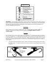
Note: Some parts are listed and shown for illustration purposes only and are not available
individually as replacement parts.
1
Note:
#8
hidden
from view.
3
4
5
6
7
Parts Diagram
2
10
9