


Page 3SKU 39213 For technical questions, please call 1-800-444-3353.
ASSEMBLY
Your Hanging Tool Cabinet, will require complete assembly as described in the
following steps. To assist you with assembly and operation, please refer to the Operational
Figures as well as the Parts List and Assembly Diagram located on the last pages of this
manual.
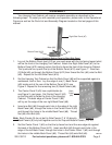
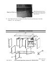
Figure 1-Attaching Bottom Panel to Right Side Panel
Lip
Right Side Panel (#7)
Bottom Panel (#12)
Bolts (#6)
1. Lay out the Bottom Panel (part #12) on your work area with the Lip facing toward what
will be the front of the Hanging Tool Cabinet. Attach the Right Side Panel (#7) to the
Bottom Panel (#12) making certain that the lip faces the front of the Hanging Cabinet.
The lip should line up with the lip of the Bottom Panel (#12)-see Figure 1. Insert two
(2) Bolts (#6) up through the Bottom Panel (#12) then thread the Nut (#5) onto the Bolt
(#6). Repeat for the Left Side Panel (#16).
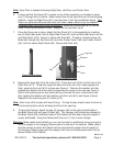
2. Set the Hanging Tool Cabinet so that the Back Panel (#8) will be supported against a
workbench, wall or oor. Lay the edge of one (1) Back Panel
(#8) inside and at the rear of the Bottom Panel (#12)-see
Figure 2. Repeat for the remaining two (2) Back Panels (#8).
The Center Panel 2 (#3) has a split/double lip-3.
see Figure 3, next page. Set Center Panel 2 (#3)
so that the split lip faces the front of the Hanging
Cabinet. The back edge of Center Panel 2 (#3)
will lay on the edge of the rear right Back Panel (#8).
Insert one Bolt (#6) through each hole in the edge of the right 4.
Back Panel (#8), through the holes in the Center Panel 2 (#3)
and through the holes in the middle Back Panel (#8). Thread
Nut (#5) onto Bolt (#6).
Note: Back Panels (8) do not bolt to Side Panels (7 & 16) directly,
Back Panels (8) only bolt together and to the Top and Bottom Panels (1 & 12).
Set the Center Panel 1 (#2) so that the lip faces front and the rear edge sits against 5.
the back of the Bottom Panel (#12). Insert one Bolt (#6) through each hole in the
edge of the left Back Panel, through the holes in the Center Panel 1 (#2) and through
the holes in the middle Back Panel (#8). Thread Nut (#5) onto Bolt (#6).
Figure 2
Back
Panel
(#8)
REV 01i