


Page 3 SKU # 42977
ASSEMBLY AND OPERATING INSTRUCTIONS
Your machine stand is fully assembled when you
receive it. However, it must be attached to the floor,
and the machine must be mounted on it prior to
operation.
1. Find a location for the stand within your
workshop. Select a location which has a sturdy,
level floor which is capable of supporting the
weight of the stand, machine to be mounted on it,
and any workpieces you intend to place on the
machine or stand.
2. The location must also provide safe working
conditions, including adequate light and
ventilation, protection from water and weather,
and acess to an appropriate power supply for the
machine.
3. Locate the stand in an area that provides
adequate working room to manage the
workpieces, tools, equipment and supplies
needed to perform the intended operations.
4. Prepare the floor by leveling it, using cement,
steel plates, wooden reinforcements or other
suitable means.
5. Place the stand in its intended location, and mark the floor through the bolt holes in the flanges on the
corners of the base.
6. Depending on the floor material, drill bolt holes or install lag bolts in the floor. Secure these as
appropriate.
7. Reposition the stand on the prepared floor fastening system, and secure in place. Test the stand to be
sure it is permanently and securely attached before placing the machine on the stand.
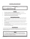
Your Drill / Mill machine may include a tray which must be positioned between the machine and the
stand. Numbers shown below refer to the diagram in Figure 1.
1. Place the tray (#5) (not included) on the stand, aligning the four holes in the corners with the mounting
holes on the upper flange of the stand.
2. With the help of an assistant, place the machine on the tray, with the mounting holes in the machine base
(#6) (not included) aligned with the holes in the tray and the stand.
3. Fasten the machine securely to the stand, using four bolts (#7), washers and nuts (not included).
4. Check to be sure the machine is securely mounted before connecting the power cord, or turning it on.
NOTE: Some parts are listed and shown for illustration purposes only
and are not available individually as replacement parts.
2
3
1
A
B
D
E
F
C
G
Figure 1. Assembly Diagram