


Page 10 For technical questions, please call 1-800-444-3353. SKU 6510
ASSEMBLY
The 10” Bench Grinder requires
minor assembly. The assembly
instructions below are written for the
left side but the right side is identical.
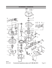
Refer to the Parts List, at the back
of this manual, for the individual part
numbers.
Tool Rest Assembly
Bolt the BENCH GRINDER UNIT (1) 1.
to a stable workplace.
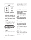
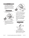
Tool Rest
Knob (8)
Tool
Rest
(7)
FIGURE 1 – Removing the Tool Rest Knob
2. Facing the front of the BENCH
GRINDER UNIT, remove the front
TOOL REST KNOB, and loosen the
rear TOOL REST KNOB (8) as in
Figure 1.
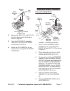
Tool Rest
Knob (8)
Tool
Rest
(7)
FIGURE 2 – Moving Tool Rest
3. Pivot the tool rest down and forward
so that it is in a horizontal position
and replace the front TOOL REST
KNOB as shown in Figure 2.
Adjust the TOOL REST (7) to the 4.
desired distance from the GRINDER
WHEEL (2). In no circumstances
should the TOOL REST be clos-
er than 1/8” from the GRINDER
WHEEL.
Tighten both TOOL REST KNOBS.5.
Eye Shield Assembly
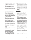
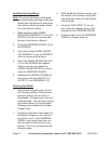
Bolts
(15)
Eye
Shield
(3)
Washers
(17)
Nuts (16)
FIGURE 3 –
Attaching the Eye Shields
and Eye Supports
1. Attach the EYE SHIELDS (3) to
the SHIELD SUPPORTS (4) using
BOLTS (15), NUTS (16), and WASH-
ERS (17) as shown in Figure 3.