


Page 4 For technical questions, please call 1-800-444-3353. SKU 68750
Specications
Rated Output 12 V~24V / 13 W
Panel Size
26-1/2 IN. L x 20-1/2 IN. W
(open position)
Note: Output will decrease as the panel gets hotter
than room temperature (~70° F). Angle, solar intensity,
cloud cover and other factors will effect output.
Installation
IMPORTANT! Read the ENTIRE IMPORTANT
SAFETY INFORMATION section at the beginning of
this manual including all text under subheadings
therein before set up or use of this product.
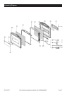
Note: For additional information regarding the
parts listed in the following pages, refer to the
Assembly Diagram near the end of this manual.
Location
1. Locate the Solar Panel where it will receive full,
unobstructed sunlight, especially during midday.
Nearby trees or tall plants will drop debris, requiring
the panel to be cleaned more frequently.
2. The installation location for panels, charge
controller/regulator, and batteries must be
inaccessible to children to prevent electric shock.
Build a childproof enclosure if needed.
3. Install the charge controller/regulator and batteries
in a weatherproof enclosure with proper ventilation.
Setup
1. Select a mounting location for the Solar Charger.
The Solar Panels (6,9) should face the Sun, and not
be blocked by shadows. The location should allow
the Panels to be protected from accidental damage.
The location should be a at, level surface able
to support the weight of the Solar Charger, and
any additional accessories. Before setup, be sure
that the main cable to either the Battery Clamp
Adaptor (20), the Barrel Plug Adaptor (21) or
either of the Car Adaptors (19,22) will reach from
the Solar Charger to the battery to be charged.
2. To setup, ip open the Solar Charger. Slide the
Support Bases (2,12) out from the Right and Left
Housing (4,10). Set the Support Rods (3,11) against
the Support Bases to lock the Bases in place.
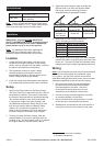
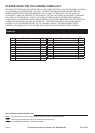
3. Adjust the Solar Charger’s angle by sliding the
Support Rods up or down the Support Bases.
See image and chart following for correct
angle depending on geographic location.
Angle 1
(around 40°)
Angle 2
(around 36°)
Angle 3
(around 30°)
Good for
Northern US
and Canada
Good for
Central US
Good for
Southern US
4. Angle face of Solar Charger toward true
south
1
according to chart that follows:
Latitude Solar Panel Angle
0-4° 10°
5-20° Latitude + 5°
21-45° Latitude + 10°
46-64° Latitude + 15°
65° or more 80°
5. Once proper location and angle have been reached,
connect the Cable (15) to the input at the back of the
power unit. The blue LED light will illuminate (ash),
indicating the Solar Charger is generating electricity.
Wiring
Note: Only a licensed electrician and a licensed building
contractor can safely design and implement a grid
tie-in system. Any grid tie-in system must meet all
applicable building and electrical codes, and must meet
standards established by the area power company.
1. Run wires from panels, through weatherproof
grommets and into enclosure where charge
controller/regulator is located. Use wires
of the proper size and rating and use twist
connectors (not included) to connect wires.
2. Connect to charge controller/regulator according
to controller/regulator’s instructions.
3. Secure all connections using terminals, or solder
all wire splices to ensure good connections.
4. Weatherproof all connections and route the wire in
a way that it will not be torn loose from the panel.
1
Angle towards true north if installed
in southern hemisphere.