


SKU 90980 Page 4
5. Set the Plastic Body (5) into the slot in the Tripod-see
Figure 2
. Tighten down
the Knob (14) on the top of the Tripod to secure the Plastic Body (5) in place-
see
Figure 2
, page 3.
6.
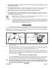
How to Level the Laser:
Note: The numbers here are only for reference, the knobs are not numbered.
a. Set the level parallel to knobs ‘1’ and ‘2’ as shown in
Leveling A.
Adjust knobs ‘1’ and
‘2’ until the Horizontal Bubble (4) is in the center.
b. Turn the level 90°. It should now be over knob ‘3’ as shown in
Leveling B
. Adjust
knob ‘3’ until the Horizontal Bubble (4) is again in the center.
c. Turn the level back 90°, to the position shown in
Leveling B
. The Horizontal Bubble
(4) should still be in the center. If it is not, repeat the steps above. If, after repeated
attempts, the level is still uneven check all mountings to ensure nothing is loose and
that the Plastic Body (5) is properly seated in the tripod slot.
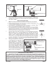
7. Once the Laser Level is set in the Tripod, you may set the laser to the type of
beam you wish to use. The laser projects up to 1,500 feet. Set the Lens
Fixture (11) “Down”; and this mode will fix the Level Laser beam to a beam
splitter (-) mode. The beam splitter mode will project a horizontal line. Set the
Lens Fixture (11) to the top mode and this mode will set the Laser Level beam
to a dot (.)-see
Figure 5
. Turn the Laser Level “ON” by pressing the “ON/OFF”
button (9) -see Figure 5. Be careful not to point the Laser Level at anyone.
8. Once you have leveled the Level Laser
in the Tripod (15), you can use it for
many applications. Rotating the
Rotating Head (7) with the laser ON
and set to the beam splitter (-) mode,
you can set a line of equal height in a
room to verify alignment of pictures,
electrical plugs, or shelving. The Laser
Level can also be used to set a level
for any surface while providing a bright
beam to mark your settings by.
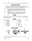
Handle (18)
Tripod (15)
Rotating
Head (7)
Figure 3
Horizontal Bubble (4)
Adjusting Knob (16)
Vertical Bubble (3)
Figure 4
Leveling A
Leveling B
REV 03/04
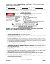
PLEASE READ THE FOLLOWING CAREFULLY
THE MANUFACTURER AND/OR DISTRIBUTOR HAS PROVIDED THE PARTS DIAGRAM IN THIS MANUAL AS A
REFERENCE TOOL ONLY. NEITHER THE MANUFACTURER NOR DISTRIBUTOR MAKES ANY REPRESENTATION OR
WARRANTY OF ANY KIND TO THE BUYER THAT HE OR SHE IS QUALIFIED TO MAKE ANY REPAIRS TO THE PRODUCT OR
THAT HE OR SHE IS QUALIFIED TO REPLACE ANY PARTS OF THE PRODUCT. IN FACT, THE MANUFACTURER AND/OR
DISTRIBUTOR EXPRESSLY STATES THAT ALL REPAIRS AND PARTS REPLACEMENTS SHOULD BE UNDERTAKEN BY
CERTIFIED AND LICENSED TECHNICIANS AND NOT BY THE BUYER. THE BUYER ASSUMES ALL RISK AND LIABILITY
ARISING OUT OF HIS OR HER REPAIRS TO THE ORIGINAL PRODUCT OR REPLACEMENT PARTS THERETO, OR ARISING
OUT OF HIS OR HER INSTALLATION OF REPLACEMENT PARTS THERETO.
Lens Fixture (11)
On/Off Button (9)
Figure 5
Battery Cover (13)
Install batteries to match
diagram