


Page 8SKU 91044 For technical questions, please call 1-800-444-3353.
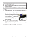
Operating the Nailer
Note: The Nailer may not work if there are only 2 or 3 nails left-see Note on page 6, bottom.
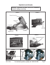
1. Set the proper angle of the Nailer for your application (a three step process):
a. Pull back and engage the Tab (70), exposing three adjustment holes. Loosen
the hex bolt and slide it into the appropriate hole (21°, 28°, 34°). Retighten the
hex bolt securely, making sure it fits into the appropriate hole properly. See
FIGURE 3. Gently release the Tab (70).
b. Remove the Adjustment Knob (81). See FIGURE 4. Move the Magazine (76)
so that the desired hole on the Plate (80) lines up with the nut on the Magazine
(76). See FIGURE 5. Replace and tighten the Adjustment Knob (81).
c. Inspect the Pin’s (34) location and compare it to FIGURE 6. If you are driving
21° angle nails the Pin should be in the lower hole (position A). If you are
driving 28° or 34° angle nails the Pin should be in the upper hole (position B).
If the Pin is in the wrong position, pull the Pin (34) out (it is held in place with a
rubber washer), reposition the Guide Plate (35), and reinsert and secure the
Pin (34). Before using the nailer, be sure that the Pin is properly secured.
2. The driving depth of a nail can be adjusted in two ways. First, by increasing or de-
creasing air pressure (never to exceed the maximum of 125 PSI). Secondly, by loos-
ening the Screw (37) and adjusting the Bracket A (38). We recommend you experi-
ment in a scrap piece of material to determine how far to adjust the unit.
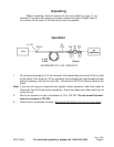
3. Attach the Nailer to the air supply at the Air Inlet (90). See FIGURE 1. Start your air
compressor and make sure it is set to between the recommended 70-125 PSI and not
over the maximum 125 PSI.
4. To fire, place the Safety (41) of the Nailer on the workpiece. The Nailer should not fire
if the Safety (41) is not depressed. Once depressed, quickly squeeze the Trigger (47)
once. Do not fire repeatedly; nails could bounce off of one another causing in-
jury. We recommend you practice with a piece of scrap material.
5. The Exhaust Cover (4) may be turned to suit your preference. See FIGURE 1 on page
7.
6. The Rubber Cover (42) provides a non-marring surface. If desired, the Rubber Cover
may be removed to expose the teeth on Safety (41). Doing so provides a nonslip
surface and can improve accuracy.
7. When finished, disconnect the Nailer from the air source.
Operation (continued)
Rev 11/06