


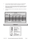
SKU 91772 For technical questions, please call 1-800-444-3353. Page 11
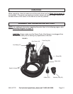
Refer to the Assembly Drawing on page 15 and FIGURE 1 on page 10.
Checking the Paint Viscosity
When using a HVLP (low pressure and high volume) spray gun the paint must be
thinned to the proper viscosity. Viscosity indicates whether the material is very liquid
(low viscosity) versus very thick (high viscosity). Viscosity is measured in the seconds it
takes for the paint to flow through the viscosity meter (DINs). Ask your paint sales repre-
sentative, check the paint container, or contact the manufacturer to find the paint’s
viscosity value.
Note: For use only with paints, never use textures or other materials. This Sprayer
can use paints with viscosity values between 10 to 14 DINs. Most commonly used
paints fall within this range and will not need to be thinned.
Always check the viscosity
of the material before using it in this Spray Gun.
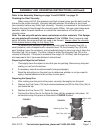
To measure the viscosity of your paint, you will need the Viscosity Cup (33), a
small container, and a timepiece with a second hand. Fill the Viscosity Cup (33) with
paint (holding it over the container), and immediately begin to time how long it takes the
Viscosity Cup (33) to empty. The time it takes to empty the Viscosity Cup (33) is the
viscosity of the paint. If the paint is outside of the range (10-14 DINs), take the appropri-
ate measures to thin it (see manufacturer’s instructions).
Preparing the Object to be Painted.
1. Thoroughly clean the object or area that you are painting. Remove any old paint,
scaling, or rust from the surface.
2. If necessary, make the surface smooth (using sandpaper).
3. Read the instructions on the paint can to determine whether or not you need to
apply a fixative/adhesive to the surface to save paint.
Preparing the Spray Gun
1. After making sure the paint is the proper viscosity, thoroughly mix the paint.
2. Remove the Cup Cover (19) (twist counterclockwise) and fill the Paint Cup (24) to
just below the top.
3. Replace the Cup Cover (19). Twist clockwise.
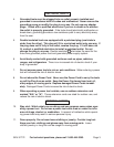
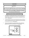
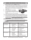
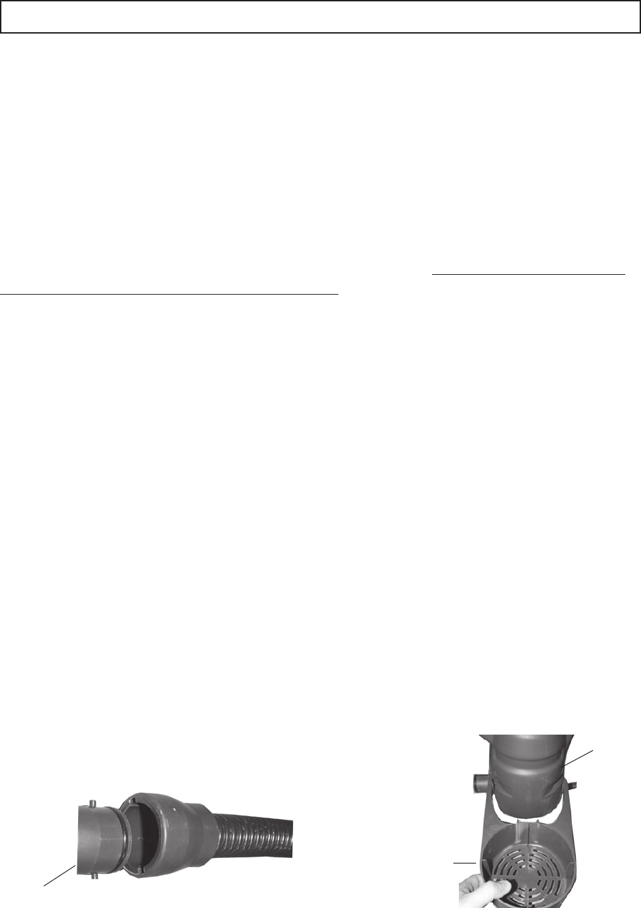
4. Connect the Spray Gun to the Spiral Air Hose (46) by snapping it into place. All
connections snap into place as illustrated in FIGURE 2 below.
FIGURE 2
Spiral Air Hose (46)
Spray Gun or Inflator
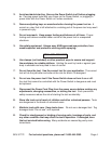
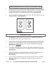
FIGURE 3
Attaching Gun Tray
ASSEMBLY AND OPERATING INSTRUCTIONS (continued)
Motor Unit
Gun Tray (41)
REV 11/05REV 11/06