


SKU 93271 For technical questions, please call 1-800-444-3353. PAGE 6
2. Pull on the Pressure Relief Valve (5A) briefly to ensure that it does not stick.
3. Turn the Air Flow Valve (6A) to its “OFF” position.
3. Connect the air hose (not provided) to the Air Flow Valve (6A) of the Air Compres-
sor. Then, connect the other end of the air hose to the pneumatic tool (not provided)
that is to be used.
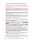
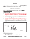
4. To extend the life of your air tools and equipment, it is recommended to install
an oiler and water filter in series (available from Harbor Freight Tools) with the Air
Output Line of the Air Compressor. (See Figure B.)
5. Note: Always plug the Power Cord of the Air Compressor into a 230V electri-
cal source.
6. Pull
up on the “ON/OFF” Power Switch (1A) to turn the Air Compressor on.
(Push
down on the “ON/OFF” Power Switch to turn the Air Compressor off.)
7. Allow sufficient time for the Tank Pressure Gauge (4A) to indicate 80 PSI before
using the Air Compressor.
8. Turn the Air Flow Valve (6A) to its “ON” position to allow air to the pneumatic tool.
9. With the Air Compressor turned on, the operation is automatic and under the control
of the automatic switches inside the box under the Power Switch (1A).
NEVER open the power switch box or adjust the controls within.
To Adjust The Air Output To The Pneumatic Tool:
1. NOTE: When adjusting the air pressure being forwarded to the pneumatic tool, you
will need to compare the pressure readings of both the Tank Pressure Gauge (3A)
and the Tool Pressure Gauge (4A). The reading on the Tank Pressure Gauge dic-
tates the maximum/minimum air pressure at which the Tool Pressure Gauge may
also be set.
2. With the Air Compressor running, and the air hose and pneumatic tool hooked up to
the Air Compressor, pull up on the Tool Pressure Adjuster (2A). Turn the Tool Pres-
TO
TOOL
AIR
COMPRESSOR
FIGURE B