


For technical questions, please call 1-800-444-3353;
Troubleshooting section at end of manual.
Page 20SKU 93793
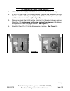
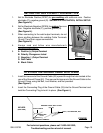
7. NOTE: The workpieces should be firmly held together and in position while welding.
Use clamps (not included) to hold the workpieces so you can concentrate on the job
at hand. The distance (if any) between the two workpieces must be controlled properly
to allow the weld to hold both sides securely while allowing the weld to penetrate
fully into the joint.
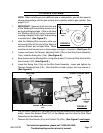
8. Set the desired welding current (35 to 140 amps) for the type of metal being welded,
using the Wire Speed Control Knob (49) and Voltage Control Knob (55).
(See Figure L.)
9. Make sure the Power Switch is in its “OFF” position. Then plug Power Cord of the
Welder into a dedicated, 230 VAC, 25 amp line with delayed action type circuit
breaker or fuse.
10. While holding the Welding Torch (51), with the Welding Wire clearly out of the way of
any grounded objects, turn the Power Switch to its “ON” position.
11. Momentarily squeeze the Trigger (51e) of the Welding Torch (51) to test the wire
feed speed. If necessary, adjust the speed by turning the Wire Speed Control Knob
(49). (See Figure L.)
12. Orient yourself on the area to be welded, then place a Face Shield over your eyes.
WARNING! Never look at the ignited arc without ANSI-approved,
arc-shaded, eye protection in a full face shield. Permanent eye damage
or blindness can occur. Skin burns can occur. Never breathe arc fumes.
(See page 8.)
HOLDING THE WELDING TORCH
13. Hold the Welding Torch (51) in one hand and the face shield in the other. If a hands-
free welding shield is used, then both hands can be used to control the Welding
Torch.
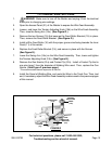
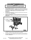
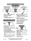
14. The Welding Wire should be directed straight into the joint.
This gives an angle of 90 degrees (straight up and down) for
groove (end to end) welds, and an angle of 45 degrees for
fillet (T-shaped) welds.
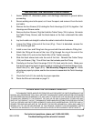
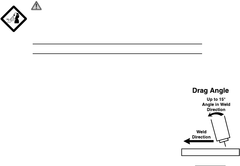
15. The end of the Welding Torch should be tilted so that the
Welding Wire is angled anywhere in between straight on and
15 degrees in the direction of the weld. The amount of tilt is
called the “drag angle”. (See Figure M.)
16. The Welding Wire should extend no more than 1/2” past the
Nozzle (51a) of the Welding Torch (51). This distance is called
“stickout”. (See Figure M.)
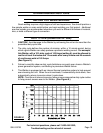
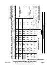
17. Set the Wire Speed and Voltage Control Knobs (49, 55) to the recommended start
settings as shown in the Weld Settings Chart on the next page. (See Figure N.)
FIGURE M