


SKU 95498 For technical questions, please call 1-800-444-3353. Page 13
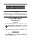
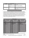
Problem Possible Cause
Possible Solution
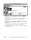
Oil discharge in air. Too much oil in 1.
crankcase.
Compressor overheated.2.
Restricted oil breather 3.
cap.
Drain crankcase and rell to proper level on 1.
sight glass.
Reduce air pressure regulation.2.
Clean or replace oil breather cap.3.
Pressure switch will not
turn off Compressor.
Defective pressure switch. Immediately unplug Compressor from its
electrical outlet. Do not operate Compressor
until a qualied service technician can replace
pressure switch.
PLEASE READ THE FOLLOWING CAREFULLY
THE MANUFACTURER AND/OR DISTRIBUTOR HAS PROVIDED THE PARTS LIST AND ASSEMBLY
DIAGRAM IN THIS MANUAL AS A REFERENCE TOOL ONLY. NEITHER THE MANUFACTURER OR
DISTRIBUTOR MAKES ANY REPRESENTATION OR WARRANTY OF ANY KIND TO THE BUYER THAT
HE OR SHE IS QUALIFIED TO MAKE ANY REPAIRS TO THE PRODUCT, OR THAT HE OR SHE IS
QUALIFIED TO REPLACE ANY PARTS OF THE PRODUCT. IN FACT, THE MANUFACTURER AND/
OR DISTRIBUTOR EXPRESSLY STATES THAT ALL REPAIRS AND PARTS REPLACEMENTS SHOULD
BE UNDERTAKEN BY CERTIFIED AND LICENSED TECHNICIANS, AND NOT BY THE BUYER. THE
BUYER ASSUMES ALL RISK AND LIABILITY ARISING OUT OF HIS OR HER REPAIRS TO THE
ORIGINAL PRODUCT OR REPLACEMENT PARTS THERETO, OR ARISING OUT OF HIS OR HER
INSTALLATION OF REPLACEMENT PARTS THERETO.
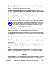
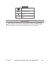
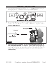
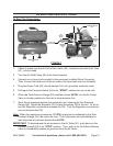
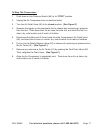
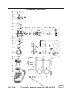
PARTS LIST
Part Description
1 Plastic Housing
2 Spring Washer
3 Washer
4 Screw (M5 x 14)
5 Fan
6 Screw (5 x 115)
7 Rear Cap
8 Washer
9 Bearing (6202)
10 Stator
11 Rotor
13 Running Capacitor
14 Bearing (6204)
15 Oil Seal
16 Nut (M8)
17 Crankcase
18 Crankshaft
19 Screw (M8 x 16 – Left hand)
20 Gasket
21 Crankcase Cover
22 Oil Sight Glass
23 Drain Plug
Part Description
24 Pan Head Screw
25 Oil Breather Cap
26 Spring Washer (#8)
27 Washer (#8)
28 Screw (M8 x 20)
29 Connecting Rod
30 Piston
31 Spring Washer
32 Piston Pin
33 Cylinder Gasket
34 Cylinder
35 Spring Washer (#6)
36 Washer (#6)
37 Screw (M6 x 40)
38 Gasket
39 Sealer Ring
40 Valve Gasket
41 Valve Plate Assy.
42 Air Intake Valve
43 Limit Pin
44 Cylinder Gasket
45 Air Filter
Part Description
46 Cylinder Head
47 Elbow Exhaust
48 Exhaust Pipe
49 Check Valve
50 Unload Pipe
51 Air Tank
52 Tank Drain Valve
53 Rubber Foot
54 Screw (M6 x 20)/Nut (M6)
55 Power Cord
56 Rubber Gasket
61 Rubber Grip
62 Safety Release Valve
63 Tank Pressure Gauge
64 Pressure Switch
65 Connector
66 Tool Pressure Gauge
67 Regulator
68 Air Outlet Valve
79 Frame Assy.
Note: Some parts are listed and shown for illustration purposes only, and are not avail-
able individually as replacement parts.
REV 08k